Loading ...
Loading ...
Loading ...
EN
29
Installation
www.bora.com
INFO The Home In contact must be bridged if this is not
used (bridged on delivery).
For connections to the Home In connection clamp, no
ferrules may be used.
Clamp the connection cable in the strain relief clamp
[4] in accordance with the wire cross section used.
INFO If external switching devices are connected both
to the Home In and Home Out interfaces, both
cables should be secured with the strain relief
claim [4].
Remove the relevant snap-out element [2] in the
plastic housing of the universal control unit.
1
2
Fig. 6.43 Home Out contacts with strain relief
[1] Strain relief clamp
[2] Snap-out element for cable feed
Check the correct installation, as well as the firm
positioning of the connection cables.
Close the cover on the universal control unit.
Make sure that the cable is not damaged.
Switch on the main switch/automatic circuit breaker.
6.11 Establishing communication and
power connection
Observe all safety and warning information (see the
Safety section).
Observe all national and regional laws and regulations
as well as the supplementary regulations of the local
utility companies.
The plug for the power supply must be accessible
following installation.
If the power supply cable has been damaged this must
be replaced.
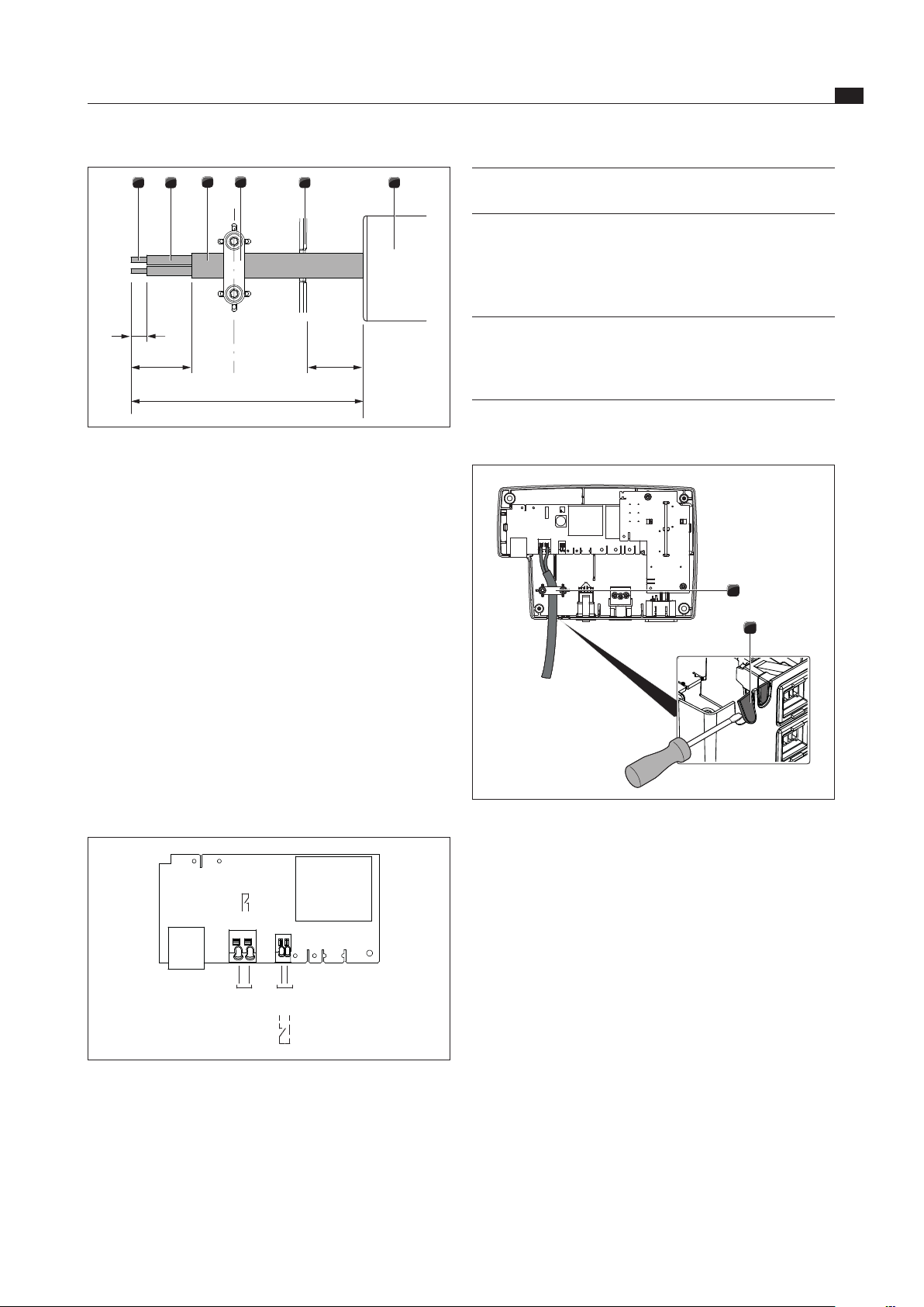
6
5
3
2
1
4
9
UFH
35
120
20
Fig. 6.41 Stripping lengths and installation position for
connection cable
[1] Stripped wire end
[2] Insulated wire
[3] Jacketed cable
[4] Strain relief clamp
[5] Cable feed snap-out element
[6] Universal ferrite sleeve (UFH)
Please adhere to the maximum stripping length of
9 mm on the stripped wire end [1].
Please adhere to the maximum stripping length of
26 mm on the insulated wire [2].
Installing the external switch device
Depending on the type of switch device, connect the
connection cables to either the Home In or the Home Out
connection clamp.
Adhere to the connection diagram when connecting
Home In and Home Out.
Home
In
Home
Out
X 7.1
X 7.2
X 6.1
X 6.2
Fig. 6.42 Connection diagram for the external switch contacts
Connect the cable for the relevant contact to the
switch contact clamp in accordance with the relevant
connection diagram (see fig. Connection diagram for
the external switch contacts).
In order to connect the Home In interface, the installed
bridge must be removed.
Loading ...
Loading ...
Loading ...