Loading ...
Loading ...
Loading ...
EN
26
Installation
www.bora.com
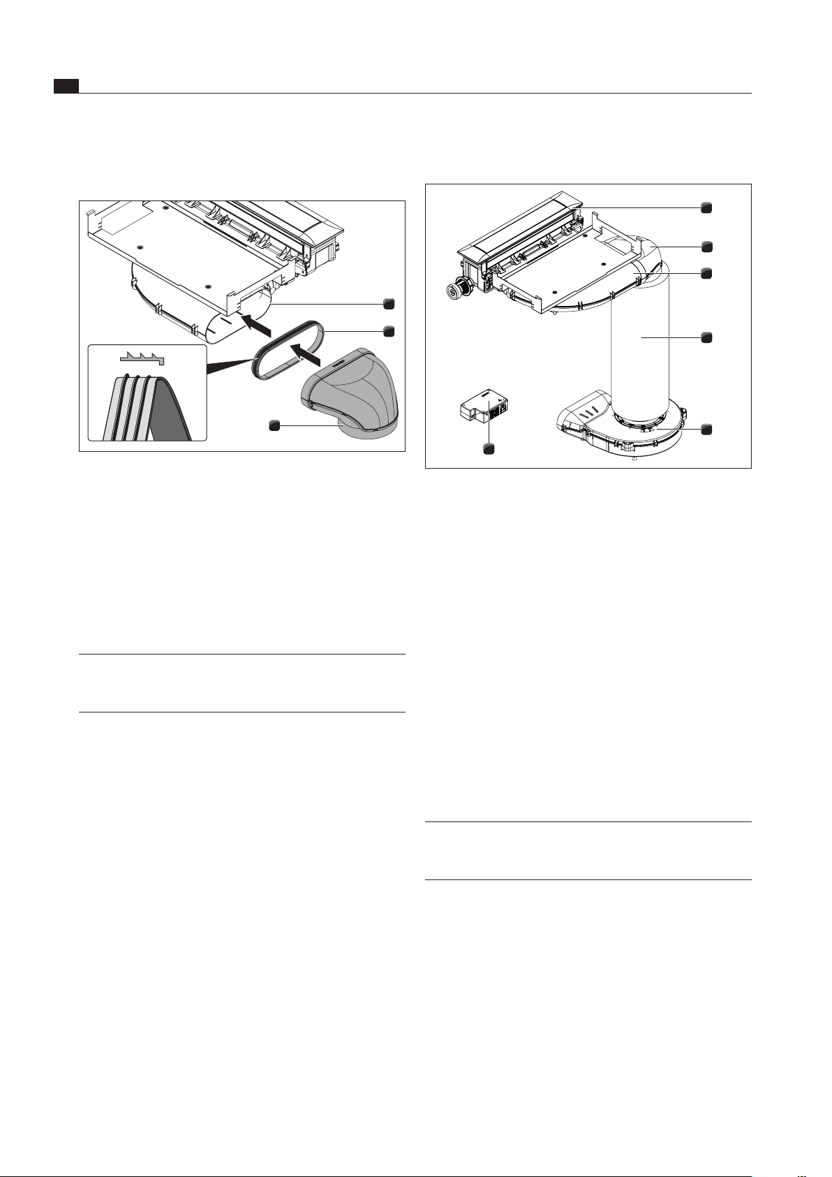
6.8.3 Standard setup PKA
1
2
3
4
5
6
Fig. 6.35 Standard setup PKA
[1] Cooktop extractor
[2] 90° diverter
[3] Bent ducting piece
[4] Silencer
[5] Universal plinth fan
[6] Universal control unit
Push the 90° diverter [2] onto the angled ducting piece
[3].
Position the plinth fan [5].
To facilitate positioning, the inlet nozzle on the plinth fan
can be removed. To do this, please see the assembly
instructions for the ULS universal plinth fan.
Connect the silencer [4] to the plinth fan [5].
Connect the silencer [4] to the 90° diverter [2].
There is also the option of gluing the connections
between the ducting sections and the plinth fan with
UDB sealing tape.
INFO Position the plinth fan and the universal control
unit in such a way that they are easily accessible
and removable for maintenance work.
The maximum exhaust air duct length with a fan is 6 m.
The minimum cross-section of the air ducts must
be 176 cm², which equates to a round pipe with
a diameter of 150 mm or the BORA Ecotube duct
system.
For the ducting, only use stable duct elements with
smooth pipe interiors. Do not use flexible or fabric
tubes.
6.8.2 Connect the duct system to the
device.
2
2
3
1
Fig. 6.34 Connecting to the duct system.
[1] Output nozzles
[2] Seal
[3] Ducting piece
Pull out the seal [2] on the connection fitting [1] of the
device. This means stretching the seal [2] slightly.
Push the duct piece [3] to be connected with the
sleeve on the connection fitting [1] with the seal [2].
Make sure the seal [2] does not move.
INFO When fitting the seal, make sure it fits and forms
an air-tight seal with the connection duct piece
when compressed.
Loading ...
Loading ...
Loading ...