Loading ...
Loading ...
Loading ...
EN
22
Installation
www.bora.com
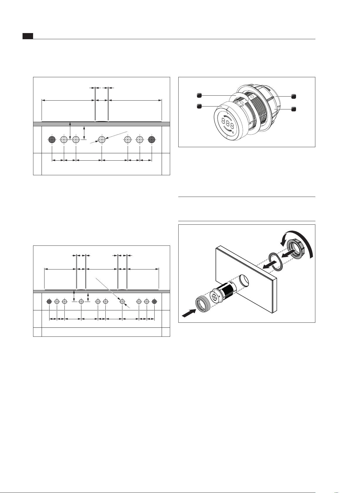
6.6.2 Fitting the control knob
3
4
2
1
Fig. 6.22 Structure of control knob
[1] Knob casing
[2] Universal nut
[3] knob ring
[4] Wave spring
INFO The wave spring must not be used with steel
fronts. The relevant assembly steps should simply
be skipped.
Fig. 6.23 Fitting the control knob
Example bore holes
≥40≥70
90 90 90
Ø50 ±0,5
90 196 196
370 370
110
1 1
Fig. 6.20 Bore holes for 2 cooktops, 2 sockets and 1 cooktop
extractor
[1] Bore holes for socket (2x external)
[2] Bore holes for control knobs (5x)
[3] Cooktop 2x
[4] Cooktop extractor
[5] Worktop
[6] Cover for the floor unit
≥70 ≥40
90 90 909090 196 196 196 196
370 370
370
110
1 1 1 1
110
Ø50 ±0,5
Fig. 6.21 Bore holes for 3 cooktops, 2 sockets and 2 cooktop
extractors
[1] Bore holes for socket (2x external)
[2] Bore holes for control knobs (8x)
[3] Cooktop 3x
[4] Cooktop extractor (2x)
[5] Worktop
[6] Cover for the floor unit
Loading ...
Loading ...
Loading ...