EN
PKA1UMEN-006
www.bora.com
Operating and installation instructions
PKA/PKAS, PKASAB
BORA Pro cooktop extractor
BORA Pro cooktop extractor system with integrated fan
BORA Pro cooktop extractor system with integrated fan All Black
1043191

Operating and installation instructions: Original Translation
Manufacturer
BORA Vertriebs GmbH & Co KG
Innstraße 1
6342 Niederndorf
Austria
Contact
T +43 (0) 5373 / 62250-0
www.bora.com
The distribution and duplication of this document, as well as the use and disclosure of its contents are prohibited
unless expressly authorised.
These operating and installation instructions have been drawn up with the greatest of care. But it cannot be ruled
out that subsequent technical modifications have not yet been incorporated or the relevant content has not yet been
adapted. Please accept our apologies in this eventuality. An updated version can be requested from the BORA Service
Team. Subject to printing errors and mistakes.
© BORA Vertriebs GmbH & Co KG
All rights reserved.

EN
3
www.bora.com
Table of Contents
1 General information 4
1.1 Target group ............................................................... 4
1.2 Validity of the operating and installation instructions 4
1.3 Other applicable documents ...................................... 4
1.4 Presentation of information........................................ 5
2 Safety 6
2.1 General safety instructions ........................................ 6
2.2 Safety instructions – Cooktop extractor .................... 6
2.3 Safety Instructions – Installation ................................ 7
2.4 Safety instructions – Cleaning and Maintenance ....... 8
2.5 Safety instructions – disassembly and disposal ......... 8
2.6 Safety instructions – spare parts ............................... 9
2.7 Use as intended ......................................................... 9
3 Technical data 10
3.1 PKA .......................................................................... 10
3.2 PKAS, PKASAB ......................................................... 11
3.3 Control knob ............................................................ 11
4 Energy consumption label 12
5 Device description 13
5.1 Type descriptions ..................................................... 13
5.2 Structure .................................................................. 13
5.2.1 Cooktop extractor PKA............................................. 13
5.2.2 Cooktop extractor system PKAS, PKASAB ............... 13
5.2.3 Grease filter components ......................................... 14
5.2.4 Control knob ............................................................ 14
5.3 Operating principle ................................................... 14
5.4 Functional principle of the cooktop extractor .......... 15
5.4.1 Power control ........................................................... 15
5.4.2 Power setting ........................................................... 15
5.4.3 Automatic cooktop extractor function ..................... 15
5.4.4 Sensors .................................................................... 15
5.4.5 Automatic after-run .................................................. 15
5.4.6 Filter service display ................................................ 15
5.4.7 Interface communication ......................................... 15
5.4.8 Safety shut-down .................................................... 15
5.4.9 Crush protection ..................................................... 15
6 Installation 16
6.1 Checking the scope of delivery ................................ 16
6.2 Tool and aids ............................................................ 16
6.3 Assembly instructions .............................................. 17
6.3.1 Safety clearances ..................................................... 17
6.3.2 Worktop and kitchen units ....................................... 17
6.3.3 Recirculation when using the cooktop extractor
as a recirculation system ......................................... 17
6.4 Cut-out dimensions .................................................. 17
6.4.1 Flush installation ...................................................... 18
6.4.2 Surface mounting ..................................................... 18
6.5 Installing the cooktop extractor ............................... 19
6.5.1 Installation dimensions ............................................ 19
6.5.2 Fitting the cooktop extractor ................................... 19
6.5.3 Securing the cooktop extractor................................ 19
6.5.4 Duct connection dimensions .................................... 21
6.6 Installing the control knob into the
floor unit front panel ................................................ 21
6.6.1 Bore hole .................................................................. 21
6.6.2 Fitting the control knob ............................................ 22
6.7 PKA planning options ............................................... 23
6.7.1 Airflow straight to the side ....................................... 23
6.7.2 Airflow to left (installation rotated around 180°) ..... 24
6.8 Installing the duct system ........................................ 25
6.8.1 Preparing for installation .......................................... 25
6.8.2 Connect the duct system to the device. .................. 26
6.8.3 Standard setup PKA ................................................. 26
6.8.4 Installing the additional fan ...................................... 27
6.9 Operating the cooktop extractor with a fireplace
that depends on the air in the room ........................ 27
6.10 Connecting external switch contacts ....................... 27
6.11 Establishing communication and power connection 29
6.11.1 Connecting the control knob .................................... 30
6.11.2 PKAS and PKASAB connections ............................... 30
6.11.3 PKA connection ........................................................ 30
6.11.4 Establishing the power connection .......................... 31
6.12 Configuration menu ................................................. 31
6.12.1 Accessing the configuration menu ........................... 31
6.12.2 Select menu option .................................................. 32
6.12.3 Changing the setting ................................................ 33
6.12.4 Exiting configuration menu ....................................... 33
6.13 Sealing the devices .................................................. 33
6.14 Handover to user ..................................................... 33
7 Operation 34
7.1 General operating instructions ................................. 34
7.2 Operating the cooktop extractor .............................. 34
7.2.1 Switching on the cooktop extractor ......................... 34
7.2.2 Automatic cooktop extractor function ..................... 34
7.2.3 Switching off the cooktop extractor ......................... 35
7.2.4 Automatic after-run ................................................. 35
7.2.5 Childproofing feature ............................................... 35
7.2.6 Crush protection ...................................................... 35
7.3 Note the filter service function ................................ 35
8 Cleaning and maintenance 37
8.1 Cleaning agents ....................................................... 37
8.2 Cleaning the cooktop extractor ................................ 37
8.2.1 Cleaning position for cover flap ............................... 37
8.2.2 Removing the cover flap, the grease filter and the
filter tray .................................................................. 37
8.2.3 Fitting the cover flap, the grease filter and the
filter tray .................................................................. 38
8.2.4 Removing the maintenance tray ............................... 38
8.2.5 Fitting the maintenance tray .................................... 39
8.2.6 Cleaning of the components .................................... 39
8.2.7 Finish cleaning the cooktop extractor ...................... 39
8.3 Cleaning the control knobs ...................................... 39
8.3.1 Cleaning the knob ring ............................................. 39
8.3.2 Cleaning the touch surface and the knob housing ... 39
8.4 Replacing the activated charcoal filter ..................... 40
9 Troubleshooting 41
10 Decommissioning, disassembly and
disposal 42
10.1 Decommissioning ..................................................... 42
10.2 Disassembly ............................................................. 42
10.3 Environmentally-friendly disposal ............................. 42
11 Warranty, technical service,
spare parts, accessories 43
11.1 BORA manufacturer’s warranty ................................ 43
11.1.1 Warranty extension .................................................. 43
11.2 Service ..................................................................... 43
11.3 Spare parts .............................................................. 43
11.4 Accessories .............................................................. 44
12 Notes: 45

EN
4
General information
www.bora.com
1 General information
1.1 Target group
These operating and installation instructions apply for the
following target groups:
Target group Requirements
User The appliance can be used by children
aged 8 and above as well as people with
reduced physical, sensory or mental
capacities or a lack of experience and/or
knowledge if they are supervised or have
been instructed how to safely use the
appliance and understand the resultant
risks. Children must be supervised. All
safety and warning information and the
handling instructions in the installation
instructions must be complied with.
Ambitious DIYers Ambitious DIYers can independently
conduct all joinery and installation work
providing they possess the necessary
skills and expertise. They must never
independently establish electricity and
gas connections.
Installation specialists Installation specialists are authorised
to conduct all joinery and installation
work in line with
existing regulations. The
electricity and gas connections must be
certified by a certified engineer for the
applicable trade prior to commissioning.
Electricians The electrical connection may only be
established by a certified engineer.
He/she also assumes responsibility for
the proper electrical installation and
commissioning.
Gas specialists The gas connection may only be
established by certified engineers.
They also assume responsibility for
proper installation and commissioning of
the gas system.
Tab. 1.1 Target groups
INFO BORA Holding GmbH, BORA Vertriebs GmbH
& Co KG, BORA APAC Pty Ltd and BORA
Lüftungstechnik GmbH - hereinafter referred to
as BORA - do not assume any liability for damage
arising from non-adherence to these documents
and from improper assembly! The electricity and
gas connections must be made by a qualified
specialist. Installation must comply with the
valid standards, regulations and laws. All safety
and warning information and the operating and
installation instructions must be complied with.
1.2 Validity of the operating and
installation instructions
These instructions apply to several device versions. It is
therefore possible that some of the features described do
not apply to your appliance.
1.3 Other applicable documents
These operating and installation instructions are valid
in conjunction with other documents, which must be
adhered to.
Please be sure to adhere to all documents that form part
of the scope of delivery.
INFO BORA accepts no liability for damage caused by
failure to comply with these documents!
Directives
This device meets the following EU/EC directives:
2014/30/EU EMC Directive
2014/35/EU Low Voltage Directive
2009/125/EC Ecodesign Directive
2011/65/EU RoHS Directive
EN
5
General information
www.bora.com
1.4 Presentation of information
To make working with these instructions quick and
easy, consistent formatting, numbering, symbols,
safety instructions, terms and abbreviations are used
throughout.
Handling instructions are market with an arrow.
Always carry out handling instructions in the sequence
shown.
Bullet points are indicated by a square bullet point at
the edge of the line.
Bullet point 1
Bullet point 2
INFO Information points out specific points you must
always comply with.
Safety and warning information
The safety and warning information in these instructions
are highlighted with symbols and signal words.
Safety and warning information is structured as follows:
WARNING SYMBOL AND SIGNAL
WORD!
Type and source of the danger
Consequences of non-compliance
Measures to minimise risk
The following applies:
The warning symbol draws attention to the danger.
The signal word indicates the severity of the risk.
Warning sign Signal word Hazard
Danger Indicates an imminent hazardous
situation which could lead to
death or serious injury
if ignored.
Warning Indicates an imminent hazardous
situation which could lead to
death or serious injury if
ignored.
Caution Indicates a potentially hazardous
situation which could lead to slight
or minor injuries if ignored.
— Caution Indicates a situation which could
result in material damage if
ignored.
Tab. 1.2 Meaning of warning symbols and signal words

EN
6
Safety
www.bora.com
2 Safety
2.1 General safety instructions
INFO The appliance complies with the
stipulated safety requirements. The
user is responsible for appliance
cleaning and maintenance as well as
its safe use. Improper use can lead
to personal injury and damage to
property.
The operating and installation instructions
contain important information about
installation and operation. These enable you
to protect yourself against injuries and
prevent damage to the appliance. Contact
details for further information as well as
application and usage questions can be found
on the back of these operating and
installation instructions.
The term “appliance” is used to refer to
cooktops, cooktop extractors or cooktops
with integrated cooktop extractor.
Read the operating and installation
instructions fully before using the appliance
for the first time.
Always store the operating and installation
instructions within easy reach so that they
can be accessed if required.
Pass the operating and installation
instructions to the next owner if you sell the
appliance.
Conduct all work extremely attentively and
conscientiously.
Check the appliance for visible damage when
unpacking it.
Do not connect a damaged appliance.
Do not connect the appliance to the mains
until the duct system has been installed or
the recirculation filter has been fitted.
Only use the connection cables supplied in
the scope of delivery.
Do not use the appliance until installation is
complete. This is the only way to ensure safe
operation.
Make sure contact with hot cooking surfaces
is not possible.
Do not place any objects on the operating
panel or the cooktop extractor air inlet nozzle.
Switch off the appliance after use.
Keep pets away from the appliance.
Unauthorised modifications
Unauthorised modifications can cause the
appliance to pose risks.
Do not make any changes to the appliance.
Households with children and people with
special needs
The appliance can be used by children aged 8
and above as well as people with reduced
physical, sensory or mental capacities or a
lack of experience and/or knowledge if they
are supervised or have been instructed how
to use the appliance safely and understand
the resultant risks.
Supervise children in the vicinity of the
appliance.
Children must not play with the appliance.
Do not store any items that could be of
interest to children in storage spaces above
or behind the appliance. Otherwise, they will
be tempted to climb onto the appliance.
Recirculation mode
INFO When cooking, additional moisture is
released into the ambient air.
INFO In recirculation mode, only a slight
amount of moisture is removed from
the cooking vapour.
When using recirculation mode, ensure a
sufficient supply of fresh air, e.g. by opening a
window.
Ensure a normal and comfortable room
climate (humidity of 45–60%), e.g. by opening
natural ventilation openings or using domestic
ventilation systems.
After every use in recirculation mode, switch
the cooktop extractor to a low level for about
20 minutes or activate the automatic after-run
function.
2.2 Safety instructions – Cooktop
extractor
Only operate the integrated cooktop extractor
with BORA cooktops. This particularly applies
to BORA gas cooktops.

EN
7
Safety
www.bora.com
CAUTION!
Exposed parts may become hot!
The cooktop extractor and its exposed
parts are hot when the cooking zone
is switched on and during the cooling
phase.
Please use suitable tools (pot
holders, oven gloves).
CAUTION!
Damage caused by objects or paper
suctioned in!
Small and light items, such as cleaning
cloths made from material or paper,
can be suctioned into the cooktop
extractor. This can damage the fan or
impair the exhaust performance.
Do not store any items or paper on
the cooktop extractor.
CAUTION!
Damage caused by grease and dirt
deposits!
Grease and dirt deposits can prevent
the cooktop extractor from functioning
properly.
Never use the cooktop extractor
without a stainless steel grease
filter.
2.3 Safety Instructions – Installation
The appliance must only be installed and
assembled by trained specialists who are familiar
with and comply with the standard national
regulations and supplementary regulations of the
local utility companies.
Work on electrical components must be
conducted by trained electrical personnel.
The electrical safety of the appliance is only
guaranteed if it is connected to a protective
conductor system that has been installed in line
with regulations. Ensure that this basic safety
precaution is met.
Check the appliance for visible damage prior
to installation.
Do not install any damaged appliance.
A damaged appliance may put your safety at
risk.
Repair and maintenance work may only be
carried out by specialists authorised by the
manufacturer.
DANGER!
Risk of smoke inhalation!
Using a replace that depends on the
air in the room produces combustion
gases.
If the cooktop extractor is used in
conjunction with a replace that
depends on the air in the room, toxic
combustion gases (carbon monoxide)
can be extracted from the chimney or
outlet duct into the living area.
Make sure that there is always a
sufficient air supply.
DANGER!
Fire risk from flambéing!
While the cooktop extractor is working,
it sucks up grease from cooking.
Flambéing food can cause the grease
to catch re.
Clean the cooktop extractor
regularly.
Never work with a naked flame while
the cooktop extractor is running.
DANGER!
Fire risk from fat deposits!
If the stainless steel grease lter is
not cleaned regularly, this can lead to
increased levels of grease in it. This
increases the re risk.
Clean and replace the filter at
regular intervals.
WARNING!
Risk of injury due to moving fan
wheel!
There is a risk of injury while the fan is
turning.
Only install the device with the
power disconnected.
Connect both sides of the fan to the
duct system before commissioning.
Ensure that the inlet nozzle is locked
before the device is commissioned
for the first time.
CAUTION!
Risk of injury from moving cover flap!
There is a risk of injury when the
electrical cover ap is moving.
Do not put your hands inside the
cooktop extractor while the cover
flap is moving.
EN
8
Safety
www.bora.com
A minimum space of 90 cm between the blow
out opening of the fan and the blow out
opening of the wall sleeve must be planned in.
2.4 Safety instructions – Cleaning
and Maintenance
The appliance must be cleaned at regular
intervals. Dirt can lead to damage or bothersome
odours. Remove dirt immediately.
Any work involving cleaning and maintenance
must not be carried out by children unless
they are supervised at all times while doing
so.
Do not use a steam cleaner for cleaning.
Steam can cause a short circuit on live parts
and thus lead to property damage (see the
Cleaning and Maintenance chapter).
When cleaning, ensure that no water
penetrates the appliance. Use only a slightly
damp cloth. Never spray the device with
water. Water penetration can cause damage!
CAUTION!
Risk of injury when inserting the
grease filter!
Injuries can be caused if the hands slip
while inserting the grease lter into the
cooktop extractor.
When inserting the grease filter, only
ever hold it by the handle provided.
2.5 Safety instructions –
disassembly and disposal
The appliance must only be disassembled by
trained specialists who are familiar with and
comply with the standard national regulations
and supplementary regulations of the local utility
companies.
Work on electrical components must only be
conducted by trained electrical personnel.
DANGER!
Risk of asphyxiation!
Packaging components (e.g. lm,
polystyrene) can be life-threatening for
children.
Store all packaging components out
of reach of children.
Dispose of the packaging properly
and immediately.
2.3.1 Safety Instructions – Cooktop
extractor
DANGER!
Risk of poisoning caused by
combustion gases!
When the cooktop extractor is used
in exhaust mode, it draws in air from
the room it is installed in and from
neighbouring rooms. Without sucient
air, there will be a drop in air pressure.
Toxic gases could be drawn out of the
chimney or extraction ducting on a
replace that depends on the room air
and back into the room.
Make sure that there is always a
sufficient air supply.
Only use reliable, tried-and-tested
switching devices, (e.g. window
contact switch, low pressure
warning device) and have them
approved by a qualified expert
(certified chimney sweep).
DANGER!
Risk of electric shock!
The control unit can contain residual
charge and cause an electric shock.
Do not touch exposed contacts on
the control unit.
DANGER!
Risk of electric shock!
Incorrect stripping of the connection
cable to external switching devices
results in a risk of electric shock.
Ensure that the connection cable is
secured with the strain relief clamp
within the universal control unit.
Ensure that the stated stripping
lengths are adhered to.
Special safety information for exhaust systems
Please pay attention to the channel length
between the fan and the wall sleeve in
straight channel design.
EN
9
Safety
www.bora.com
DANGER!
Risk of electric shock!
Incorrectly disconnecting the appliance
from the mains results in a risk of
electric shock.
Securely disconnect the appliance
from the mains using LS switches,
fuses, automatic circuit breakers or
contactors.
Use an authorised measuring device
to ensure that there is no power to
the appliance.
Do not touch exposed contacts on
the electronic unit as they can
contain residual charge.
2.6 Safety instructions – spare parts
WARNING!
Risk of injury and damage to
property!
Incorrect components can lead to
personal injury or damage to the
appliance. Modications, additions or
alterations to the appliance can lead to
safety risks.
Only use original spare parts for
repairs.
INFO A damaged power supply cable must
be replaced by a suitable power supply
cable. This may only be done by an
authorised member of the After Sales
Service team.
2.7 Use as intended
The appliance cannot be used at altitudes above
2,000 m (metres above sea level).
The appliance is solely intended for preparing
food in private households. This appliance is not
intended for:
Outdoor use
Installation in vehicles
Heating rooms
Use in non-stationary installation sites (e.g. on
ships)
Use with an external timer or a separate
remote control system (remote operation)
Any use other than that specified in these
operating and installation instructions or any use
that goes beyond that which is described here is
classed as unintended. BORA does not assume
any liability for damages caused by improper use
or incorrect operation.
All misuse is prohibited!
INFO BORA Holding GmbH, BORA Vertriebs
GmbH & Co KG, BORA APAC Pty Ltd
and BORA Lüftungstechnik GmbH do
not assume any liability for damage
arising from non-adherence to the
safety and warning information.
EN
10
Technical data
www.bora.com
3 Technical data
3.1 PKA
Parameter Value
Supply voltage 220 - 240 V
Frequency 50/60 Hz
Power consumption (including external
BORA universal article fans)
max. 700 W
Dimensions (width x depth x height) 482 x 540 x 176 mm
Dimension of control knob
(diameter x depth)
Ø 49 mm
Ø 92 mm
Weight (incl. accessories/packaging) 9.25 kg
Cooktop extractor
Power levels 1 - 9, P
Tab. 3.1 Technical data PKA
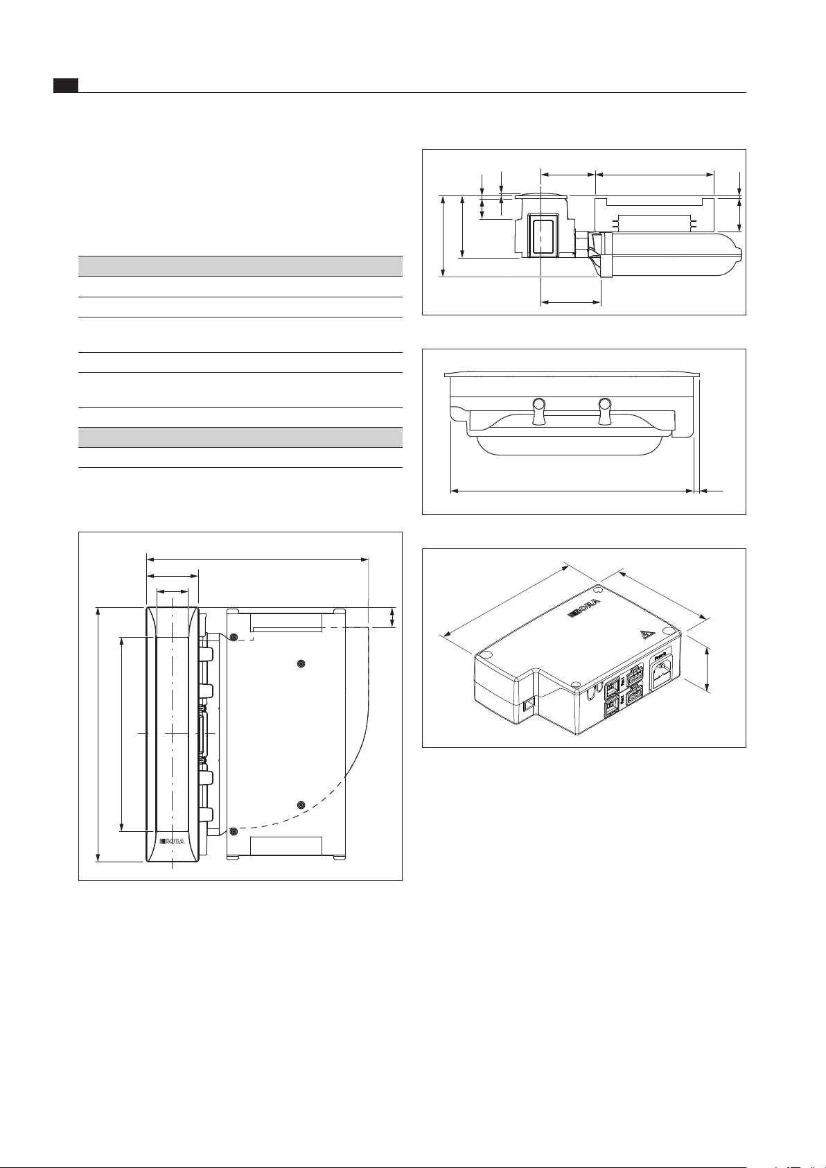
Device dimensions PKA
110
482
540
411
67
43
Fig. 3.1 PKA Device dimensions aerial view
115 252
5,571,5
176
40
7
6
126
138
Fig. 3.2 PKA Device dimensions front view
12
516
Fig. 3.3 PKA Device dimensions side view
187
60
128
Fig. 3.4 Universal control unit device dimensions
EN
11
Technical data
www.bora.com
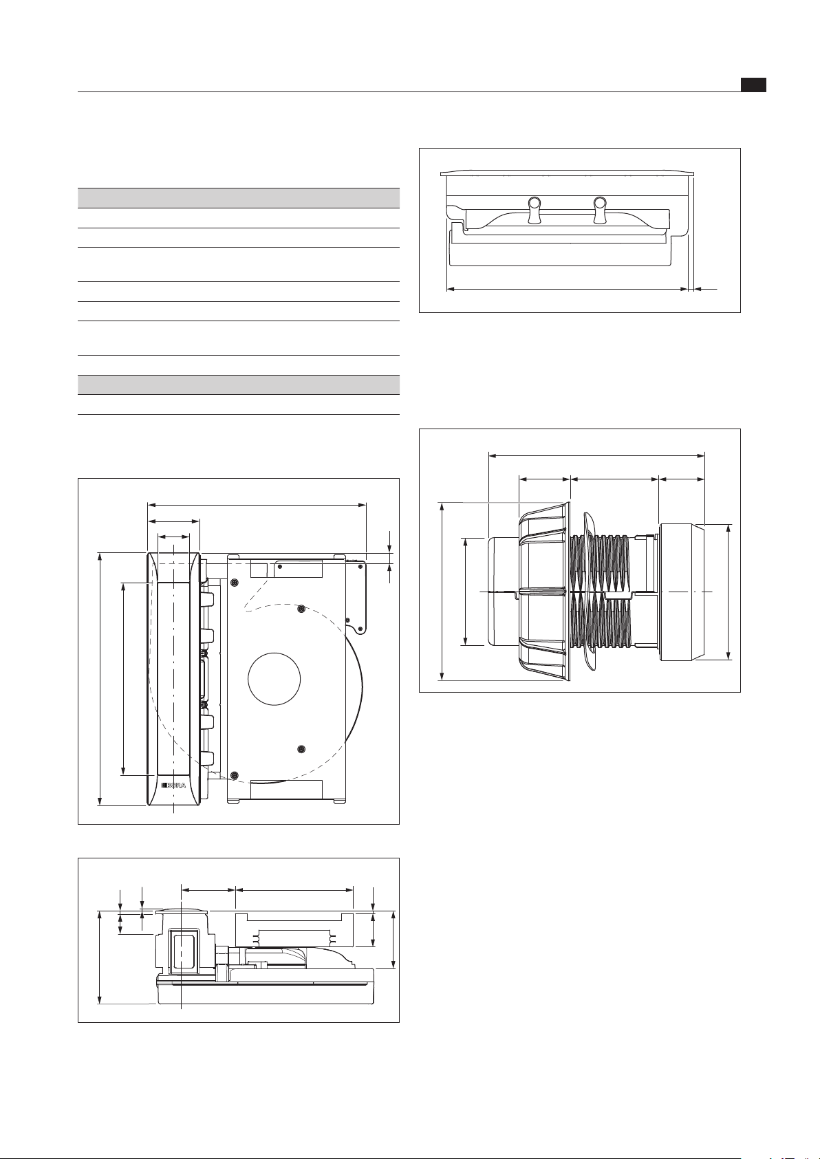
12
516
Fig. 3.7 PKAS, PKASAB Device dimensions side view
3.3 Control knob
Device dimensions control knob
Ø49
Ø58
Ø76
92
22 10-40 20
Fig. 3.8 Device dimensions control knob
3.2 PKAS, PKASAB
Parameter Value
Supply voltage 220 - 240 V
Frequency 50/60 Hz
Power consumption (including external
BORA universal article fans)
max. 700 W
Power consumption of internal motor max. 170 W
Dimensions (width x depth x height) 468 x 540 x 199 mm
Dimension of control knob
(diameter x depth)
Ø 49 mm
Ø 92 mm
Weight (incl. accessories/packaging) 12.5 kg
Cooktop extractor
Power levels 1 - 9, P
Tab. 3.2 Technical data PKAS, PKASAB
Device dimensions PKAS, PKASAB
23
110
468
540
411
67
Fig. 3.5 PKAS, PKASAB Device dimensions aerial view
115 252
5,571,5
123
199
40 7
6
Fig. 3.6 PKAS, PKASAB Device dimensions front view
EN
12
Energy consumption label
www.bora.com
4 Energy consumption label
Product description Professional
cooktop extractor PKA
Professional
cooktop extractor system PKAS, PKASAB
Operating mode Exhaust air Exhaust air
Energy consumption Value Value EN standard
Annual energy consumption (AEC
hood
) 23.4 kWh/a 32.5 kWh/a 61591
Energy efficiency class A++ A+ 61591
Energy efficiency index (EEI
hood
) 31.6 42.5 61591
Flow volume
Fluid dynamic efficiency (FDE
hood
) 38.4 34.5 61591
Fluid dynamic efficiency class A A 61591
Minimum air flow 276.9 m³/h 251.7 m³/h 61591
Maximum air flow 612.7 m³/h 618.2 m³/h 61591
Air flow power setting (Q
Max
) 612.7 m³/h 689.8 m³/h 61591
Lighting
Lighting efficiency (LE
hood
) * lx/Watt * lx/Watt *
Lighting efficiency class * * *
Grease filtering
Maximum level (no power setting) (GFE
hood
) 86.8 % 91.28 % 61591
Class maximum level B B 61591
Sound power level
minimum 42.5 dB(A) 47.6 dB(A) 60704-2-13
maximum 61.5 dB(A) 68.4 dB(A) 60704-2-13
Power setting 61.8 dB(A) 69.9 dB(A) 60704-2-13
Sound pressure level (additional details)
minimum 29.2 dB(A) 34.9 dB(A) **
maximum 48.2 dB(A) 55.7 dB(A) **
Power setting 48.5 dB(A) 57.2 dB(A) **
Details according to 66/2014
Time increase factor 0.6 0.8 61591
Electric power input at the best efficiency
point (W
BEP
)
106.9 W 111.3 W 61591
Pressure at the best efficiency point (P
BEP
) 518 Pa 418 Pa 61591
Air flow rate at the best efficiency point (Q
BEP
) 288.1 m³/h 330.7 m³/h 61591
Power consumption in off mode (P
O
) 0.4 W 0.43 W 61591
Tab. 4.1 Information on the energy consumption label in accordance with Ordinance (EU) no. 65/2014 or 66/2014.
* This specification is not applicable for this product.
** The sound pressure level has been determined from a distance of 1m (distance-dependent level recording) on the
basis of the sound power level established in EN 60704-2-13.
EN
13
Device description
www.bora.com
5 Device description
Observe all safety and warning information during
operation (see the Safety section).
The cooktop extractor has the following features:
Power control via a control knob
Power display
Electrical cover flap with position sensor
Stainless steel grease filter
Grease filter position sensor
Automatic cooktop extractor function
Automatic after-run
Filter service display
Interface for external devices
Safety shut-down
Cover flap crush protection
Depending on the model you purchased, the cooktop
extractor can be operated as an exhaust air or an
recirculating air version.
Exhaust mode
The air extracted is cleaned by the stainless steel grease
filter and released outside through a duct system.
The exhaust air must not be expelled into:
a smoke or exhaust gas flue that is in operation
a shaft used for the aeration of rooms where fireplaces
are installed.
If the exhaust air is to be directed into a smoke or
exhaust gas flue that is not in use, the installation must
be checked and approved by the responsible heating
engineer.
Recirculation mode
The air extracted is purified by the grease filter and an
activated charcoal filter and fed back into the room in
which the appliance is installed.
To prevent odours in recirculation mode, an odour
filter must be used. For hygiene and health reasons,
the activated charcoal filter must be replaced at
the recommended intervals (see the Cleaning and
maintenance section).
INFO In recirculation mode, ensure sufficient ventilation
and aeration to expel humidity.
5.1 Type descriptions
PKA = Professional cooktop extractor with separate
control unit and freely combinable fans
PKAS, PKASAB = Professional cooktop extractor
system with built-in control unit and built-in fans
5.2 Structure
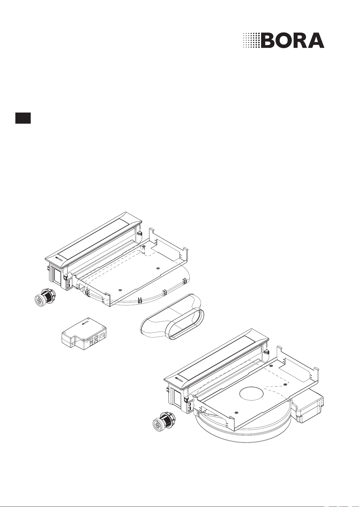
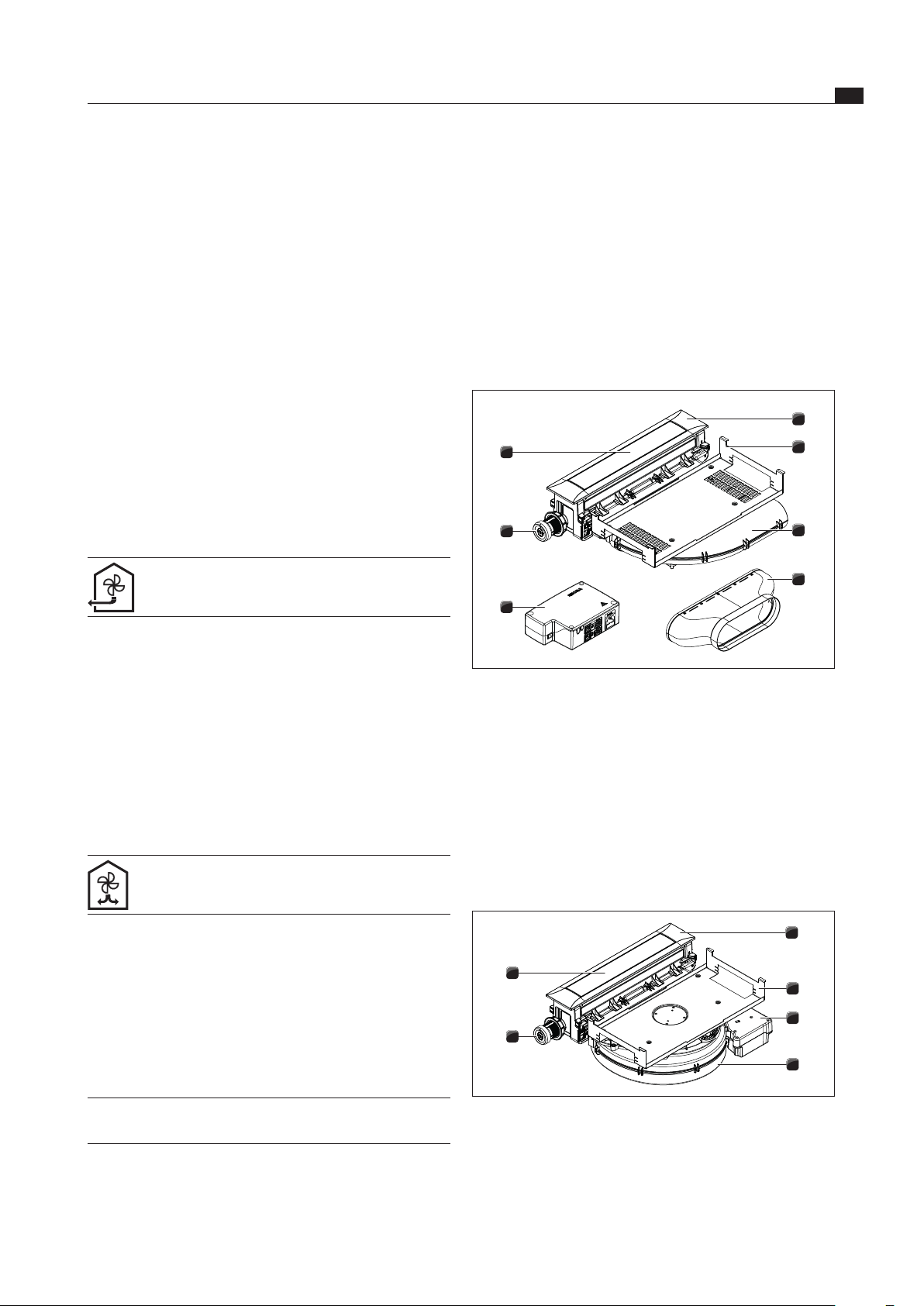
5.2.1 Cooktop extractor PKA
7
6
5
4
3
2
1
Fig. 5.1 Cooktop extractor PKA
[1] cover frame
[2] Holding plate
[3] Bent ducting piece
[4] Straight ducting piece
[5] Universal control unit
[6] Control knob
[7] Cover flap
5.2.2 Cooktop extractor system PKAS,
PKASAB
6
5
3
4
2
1
Fig. 5.2 Cooktop extractor system PKAS, PKASAB
[1] cover frame
[2] Holding plate
[3] Control unit
[4] Fan housing with fan
[5] Control knob
[6] Cover flap
EN
14
Device description
www.bora.com
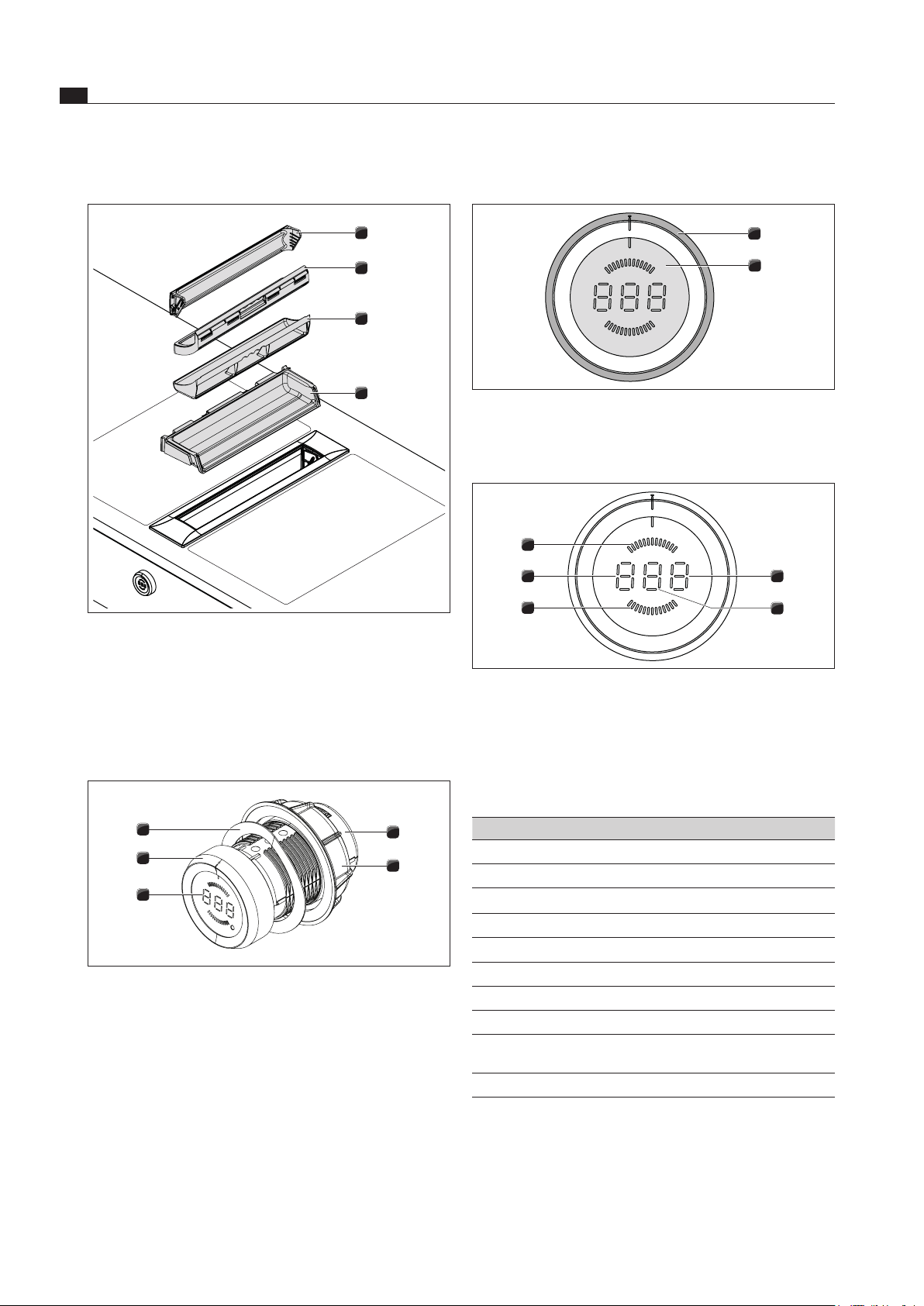
5.2.3 Grease filter components
4
3
2
1
Fig. 5.3 Grease lter components
[1] Cover flap
[2] Stainless steel grease filter
[3] Filter tray
[4] Maintenance tray
5.2.4 Control knob
4
3
5
2
1
Fig. 5.4 Control knob
[1] Knob casing
[2] Universal nut
[3] Control knob display
[4] knob ring
[5] Wave spring
5.3 Operating principle
2
1
Fig. 5.5 Control elements of control knob
[1] knob ring
[2] Touch surface
5
4
3
2
1
Fig. 5.6 Control knob display elements
[1] Display of functions
[2] Power display
[3] Recirculation display
[4] Display of mode or operating mode
[5] Exhaust mode display
Control knob display Meaning
1 - 9
Power levels
P
Power setting
0
Cooktop extractor is switched off
A
+ Power level
Extraction system
n
Automatic after-run
L
Childproofing feature active
c
Cleaning position for cover flap
F
flashing
Filter service display
E
...
Error message
(see Troubleshooting section)
C
Configuration menu
Tab. 5.1 Meaning of display
Knob operation
The cooktop extractor is operated using a control knob.
By twisting the control knob and pressing the touch
surface, the power levels and functions are controlled
(see Operation section).

EN
15
Device description
www.bora.com
5.4.5 Automatic after-run
The cooktop extractor continues to run at a lower level
and switches off automatically after 20 minutes.
5.4.6 Filter service display
The filter service display is active after 200, 300 or
400 operating hours, depending on the filter unit fitted.
The activated charcoal filter has reached the end of its
service life (with recirculation only) and the grease filter
components need to be thoroughly cleaned.
After the cooktop extractor is switched on, F flashes
on the control knob display.
The filter service display is shown every time the
cooktop extractor is switched on and remains active
until the filter has been changed and the filter service
display has been reset.
The cooktop extractor can still be operated without
limitations.
The filter service display can be deactivated on a
one-off basis or completely reset in order to use the
cooktop extractor.
INFO
Irrespective of the filter service display, the grease
filter components require regular cleaning (see
Cleaning and maintenance section).
5.4.7 Interface communication
The internal interface can be used for extended control
options. This has a ‘Home In’ and a ‘Home Out’ contact
(see the Installation section).
The ‘Home In’ contact can be used for the signal input
from external switch devices (e.g. window contact
switch).
The ‘Home Out’ contact can be used to control
external installations.
5.4.8 Safety shut-down
The cooktop extractor shuts down automatically after an
operating time of 120 minutes with no changes in power
level.
5.4.9 Crush protection
The electrical cover flap on the cooktop extractor has
crush protection.
If the cover flap is blocked while it is opening or closing,
the movement is stopped automatically. The cover
flap moves back to its starting position (see Operation
section).
5.4 Functional principle of the
cooktop extractor
5.4.1 Power control
The power levels are controlled by turning the knob ring
to the desired power level.
5.4.2 Power setting
The cooktop extractor has a power-enhancing power
setting. This power setting makes it possible to suction
away high levels of cooking vapours more quickly. After
9 minutes, the power setting is automatically switched to
power level 9.
5.4.3 Automatic cooktop extractor function
The automatic cooktop extractor function adjusts the
extraction performance automatically to the highest
power level for all cooking zones connected.
Function Power levels
Cooking level 1 2 3 4 5 6 7 8 9 P
Extraction power 4 4 4 4 5 6 7 8 9 P
Tab. 5.2 Extraction performance and cooking level
If the power level of the cooking zones is changed,
the automatic cooktop extractor function adjusts the
cooktop extractor performance after a 30 second delay.
Once the cooking session is complete, the automatic
after-run is activated.
After the automatic after-run period, the cooktop
extractor switches itself off automatically.
5.4.4 Sensors
The cooktop extractor is fitted with sensors near the
cover flap and the grease filter.
Position sensor for cover flap
The cover flap sensor detects the position of the cover
flap.
If the cover flap is closed, the cooktop extractor is
deactivated.
If the cover flap is open, the cooktop extractor can be
used.
If the cover flap is removed, the cooktop extractor can
be used.
Grease filter position sensor
The grease filter sensor detects whether the grease filter
is properly fitted.
If the grease filter is missing or fitted incorrectly, the
cooktop extractor is deactivated.
INFO If the grease filter has been removed, for example
for cleaning purposes, the cover flap can still be
closed.
EN
16
Installation
www.bora.com
6 Installation
Observe all safety and warning information
(see the Safety section).
INFO The device must not be installed above cooling
devices, dishwashers, stoves, ovens, washing
machines or dryers.
INFO The contact surfaces of the worktops and wall
sealing strips must be made of a heat-resistant
material (up to approx. 100 °C).
INFO Worktop cut-outs must be moisture-sealed using
suitable means and, where necessary, fitted with
a thermal insulator.
NFO Control knobs have to be connected only to the
provided connections of the cooktop extractor.
6.1 Checking the scope of delivery
Check the scope of delivery to make sure everything
has been provided (see table (see Table 6.1 and 6.2).
If there are any missing or damaged parts, please
notify BORA After Sales Service.
Do not under any circumstances install parts which are
damaged.
Dispose of transport packaging in the proper manner
(see the Decommissioning, disassembly and disposal
section).
Scope of delivery PKA
Name Quantity
Operating and installation instructions 1
Cooktop extractor 1
Height adjustment plate set 1
Mounting clamps 4
Control knob 1
Stainless steel grease filter 1
Filter tray 1
Maintenance tray 1
Cover flap 1
CAT 5 communication cable 1
Universal control unit 1
Power supply cable 1
Straight ducting piece 1
Control knob cable – interface/extractor 1000 mm 1
Tab. 6.1 Scope of delivery PKA
Scope of delivery PKAS, PKASAB
Name Quantity
Operating and installation instructions 1
Cooktop extractor 1
Height adjustment plate set 1
Mounting clamps 4
Control knob 1
Stainless steel grease filter 1
Filter tray 1
Maintenance tray 1
Cover flap 1
Power supply cable 1
Control knob cable – interface/extractor 250 mm 1
Tab. 6.2 Scope of delivery PKAS, PKASAB
6.2 Tool and aids
The following tools are required to correctly install the
cooktop extractor:
Pencil
Tape measure or metre rule
Standard or cordless drill with Forstner bit Ø50 mm
Black, heat-resistant silicone sealant
Flat screwdriver
Torx screwdriver size 20
Torx screwdriver size 10 (PKA only)
EN
17
Installation
www.bora.com
6.3.3 Recirculation when using the cooktop
extractor as a recirculation system
In the case of recirculation systems there must be a
return flow aperture in the kitchen units:
> 500 cm² (per air cleaning box) in combination with
cooktops PKFI11, PKI11, PKIW1, PKC32, PKC3B,
PKCH2 and PKT11
> 1000 cm² (per air cleaning box) in combination with
gas cooktop PKG11
INFO If several extractor systems are operated in
recirculation mode, the return flow aperture
for each air cleaning box must be calculated
correspondingly.
Example:
2 recirculation systems = 2 x (> 500 cm²) or
2 x (> 1,000 cm²) in the case of gas appliances
For recirculation, the necessary return flow aperture can
be created using a shortened plinth. A slatted plinth with
at least the minimum opening cross-section can also be
used.
Ensure that the return flow aperture is large enough.
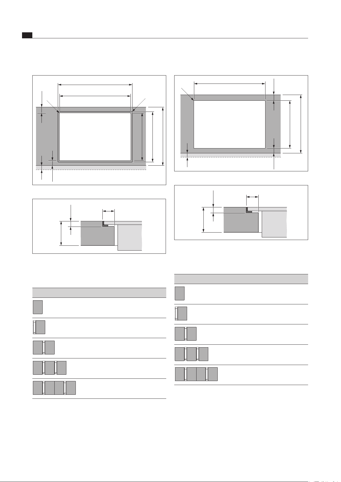
6.4 Cut-out dimensions
INFO All dimensions from the front edge of the front
cover.
Worktop overhang
≥60
(
≥74
)
14x
Fig. 6.2 Worktop overhang
Please note the worktop overhang x when creating
the worktop cut-out. Applies to flush installation and
surface mounting.
INFO For cooktop extractor PKA used in conjunction
with straight ducting piece PKA1FEV, flush
mounting is also possible for worktop depths
≥ 650 mm.
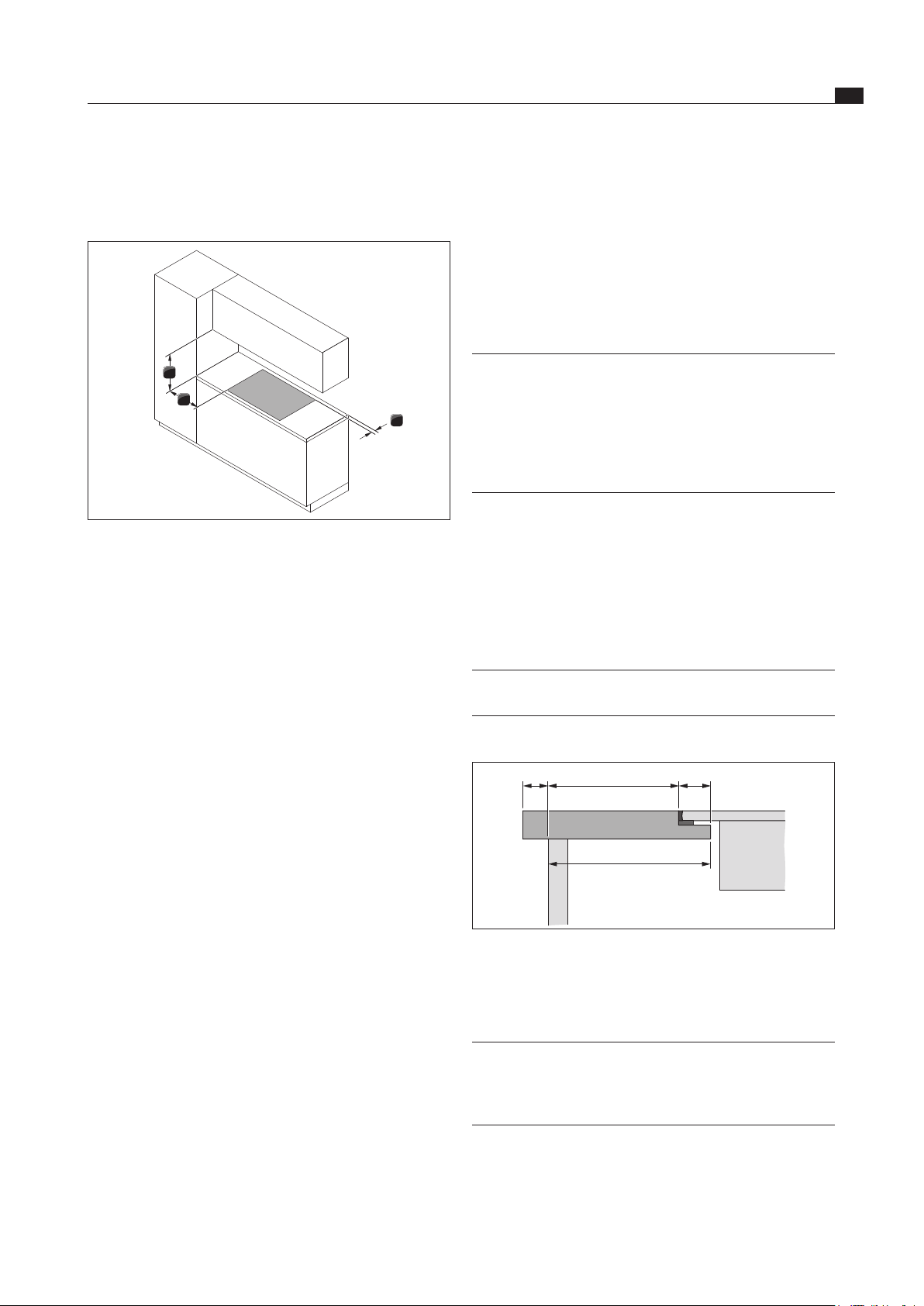
6.3 Assembly instructions
6.3.1 Safety clearances
1
3
2
Fig. 6.1 Recommended minimum clearances
Maintain the following safety clearances:
[1] Rear minimum clearance of 50 mm between the worktop
cut-out and the rear corner of the worktop.
[2] Minimum clearance of 300 mm from the left and right of the
worktop cut-out to the adjacent cabinet or wall.
[3] Minimum clearance of 600 mm between the worktop and
the wall unit.
6.3.2 Worktop and kitchen units
Create the worktop cut-out taking into account the
specified cut-out dimensions.
Make sure that the cutting surfaces of the worktops
are properly sealed.
Comply with the instructions of the worktop
manufacturer.
Cross bars on the kitchen unit in the area of the
worktop cut-out may need to be removed.
No false floor is necessary below the cooktop. If cable
protection (false floor) is planned, the following must
be taken into account:
It must be fitted in such a way that it can be
removed for maintenance work.
To ensure sufficient cooktop ventilation, a minimum
distance of 15 mm to the bottom edge of the
cooktop is to be observed.
The drawers and/or shelves in the floor unit must be
removable.
For correct installation, the slide-in units of the
base cabinet must be shortened depending on the
installation situation.
EN
18
Installation
www.bora.com
6.4.2 Surface mounting
x
B ±2
≤ R5
≥ 74
(≥ 70)
516 ±2
≥ 700
Fig. 6.5 Cut-out dimensions surface mounting
7 +0,5
14
10 - 40
Fig. 6.6 Surface mounting cut-out
Cut-out dimensions when installing cooktops only or
cooktops and the cooktop extractor next to each other:
Cooktops/cooktop extractor B in mm
1/0 346
1/1 457
2/1 828
3/2 1310
4/2 1681
Tab. 6.4 Cut-out dimensions appliance combinations surface
mounting
6.4.1 Flush installation
x
A ±2
B ±2
544 ±2
≤ R5
≤ R5
≥ 74
(≥ 70)
516 ±2
≥ 700
Fig. 6.3 Cut-out dimensions ush installation
7 +0,5
14
10 - 40
Fig. 6.4 Groove dimensions for ush installation
Cut-out dimensions when installing cooktops only or
cooktops and the cooktop extractor next to each other:
Cooktops/cooktop extractor A in mm B in mm
1/0 374 346
1/1 485 457
2/1 856 828
3/2 1338 1310
4/2 1709 1681
Tab. 6.3 Cut-out dimensions appliance combinations ush
installation
EN
19
Installation
www.bora.com
1
2
Fig. 6.9 Height adjustment plates
[1] Height adjustment plate
[2] Cooktop extractor
If applicable, insert the height adjustment plates [1].
0,5
21 1
Fig. 6.10 Installing the cooktop extractor
[1] Cooktop
[2] Cooktop extractor
The cooktop extractor [2] must be installed 0.5 mm
higher than the cooktops [1].
6.5.3 Securing the cooktop extractor
The cooktop extractor is secured using the four mounting
brackets provided. The mounting brackets have offset
fastening lugs, with one side for surface mounting and
one for flush mounting. The mounting clamps can be
adjusted to the thickness of the worktop.
6.5 Installing the cooktop extractor
INFO Clearance of one millimetre should be planned
between the built-in appliances.
In combination with an adjacent PKIW1 induction
wok cooktop, the plastic strip on the side of the
cooktop extractor must be carefully removed for
this.
INFO A clearance of two millimetres should be planned
around the built-in appliances.
6.5.1 Installation dimensions
≥700
≥900
≥74
Fig. 6.7 PKA, PKAS and PKASAB device installation dimensions
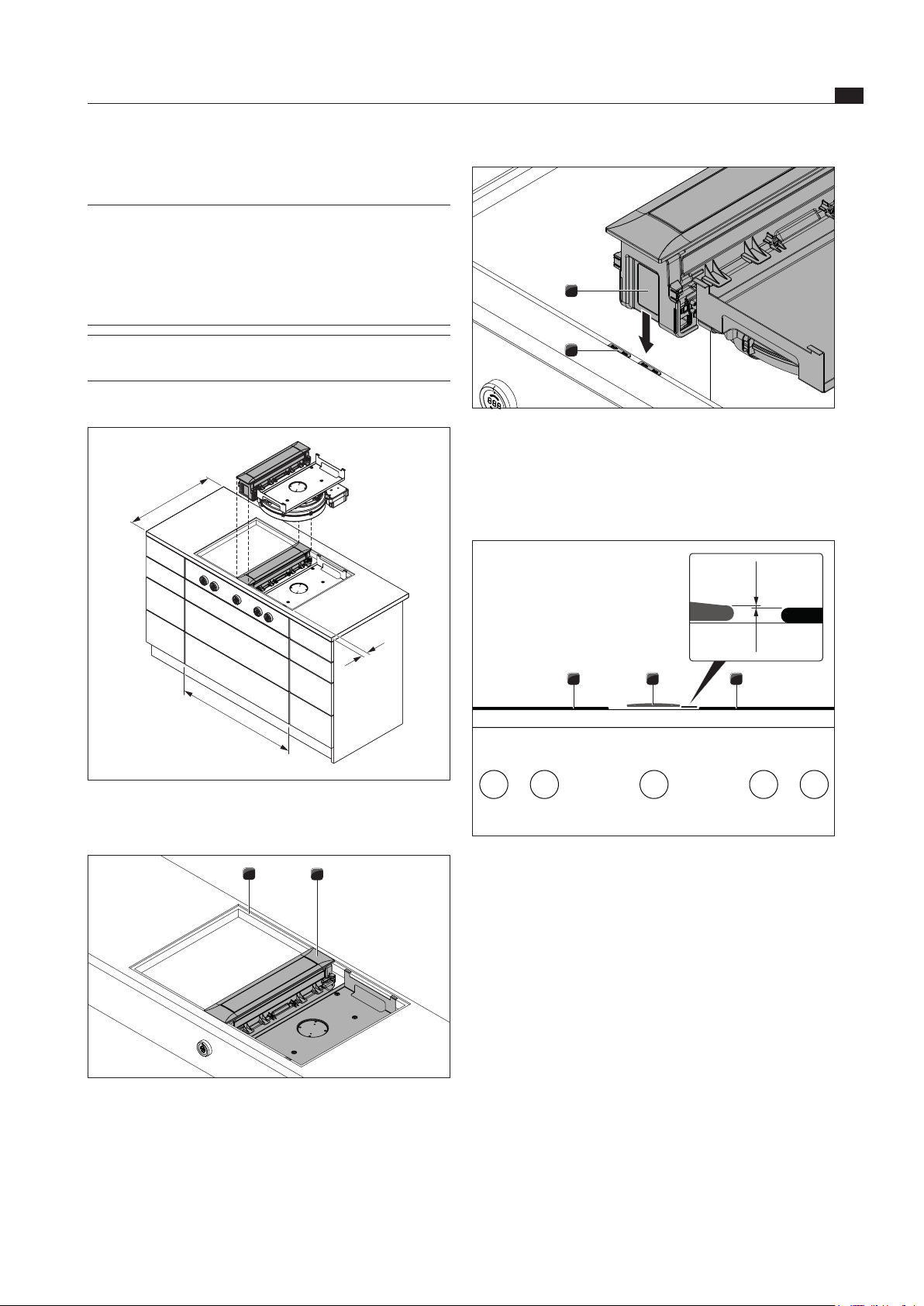
6.5.2 Fitting the cooktop extractor
1
2
Fig. 6.8 Fitting the cooktop extractor
[1] Worktop cut-out
[2] Cooktop extractor
Place the cooktop extractor [2] in the middle of the
relevant worktop cut-out [1].
Precisely position the cooktop extractor [2].
EN
20
Installation
www.bora.com
If necessary, shorten the mounting clamps in line with
the worktop thickness.
To do this, cut the mounting clamps at the appropriate
cut marks using a cutter.
Depending on the installation type, twist the mounting
clamps to the left or right (flush mounting or surface
mounting).
Securing the cooktop extractor
INFO The cooktop extractor is secured using the four
mounting clamps provided, for which there are 4
alternative positions on the holding plate.
23 1
Fig. 6.13 Push on mounting clamps
[1] Alternative position for mounting clamp
[2] mounting clamp
[3] Cooktop extractor
Push the mounting clamps [2] into the holders
provided on the cooktop extractor [3] or the alternative
positions on the holding plate [1].
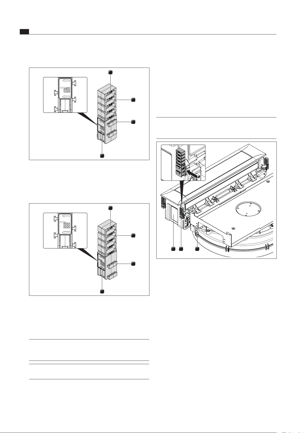
Preparing the mounting clamps
4
3
2
1
Fig. 6.11 Mounting clamp on right (ush mounting)
[1] Worktop thickness labelling (in mm)
[2] Cut mark (4x)
[3] Fastening lugs (2 on each side)
[4] Marking for flush mounting
4
3
2
1
Fig. 6.12 Mounting clamp on left (surface mounting)
[1] Worktop thickness labelling (in mm)
[2] Cut mark (4x)
[3] Fastening lugs (2 on each side)
[4] Marking for surface mounting
INFO The symbols on the mounting clamps show which
side to use for surface mounting and for flush-
mounting.
INFO The labels shows the cutting mark to go with the
worktop thickness.
EN
21
Installation
www.bora.com
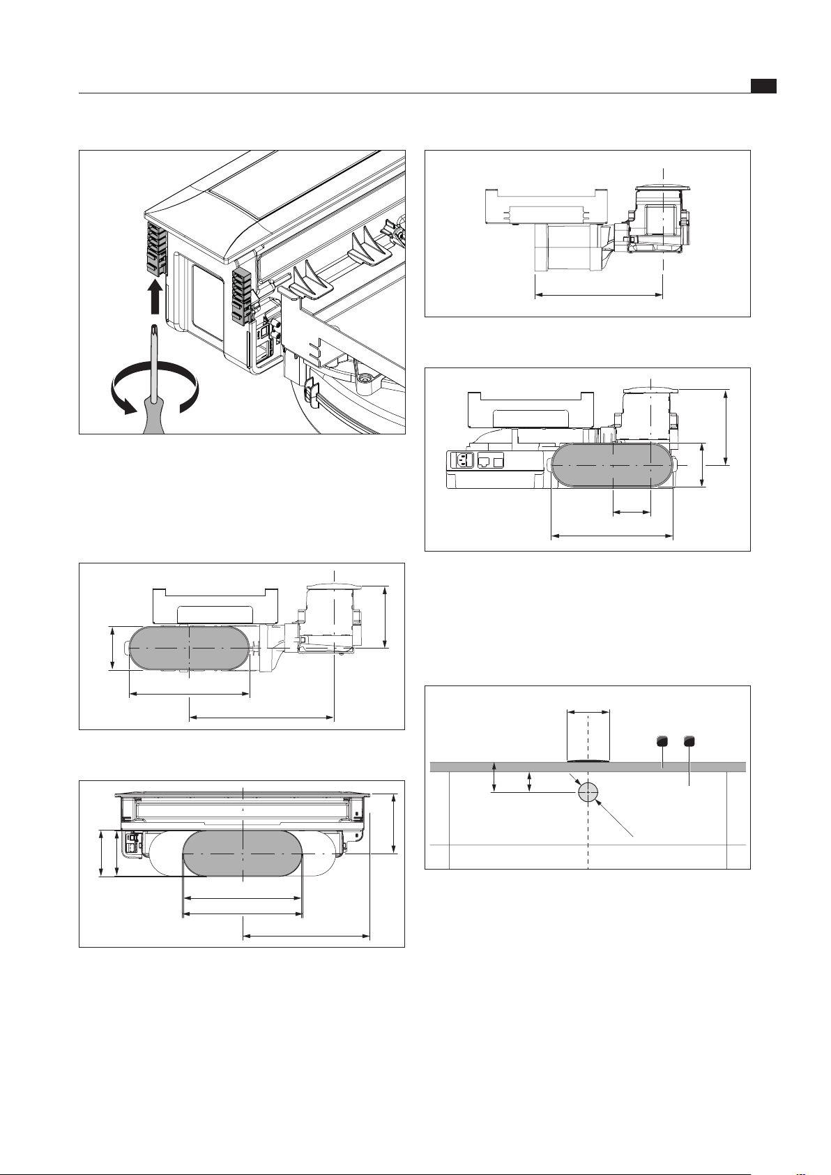
265
Fig. 6.17 PKA duct connection dimensions with straight ducting
piece
245
78
89
151
Fig. 6.18 PKAS, PKASAB duct connection dimensions
6.6 Installing the control knob into
the floor unit front panel
6.6.1 Bore hole
≥40≥70
1 2
Ø50 ±0,5
110
Fig. 6.19 Drill template
[1] Worktop
[2] Fixed front panel
Pre-drill the bore hole to prevent tearing out the panel.
Fig. 6.14 Tighten the mounting clamps
Use a Torx 20 screwdriver to tighten the mounting
clamps slightly from underneath.
Verify that the alignment is correct.
6.5.4 Duct connection dimensions
245
294
89
126
Fig. 6.15 PKA duct connection dimensions with angled ducting
piece
255
245
89
99
126
270
Fig. 6.16 PKA duct connection dimensions with straight ducting
piece
EN
22
Installation
www.bora.com
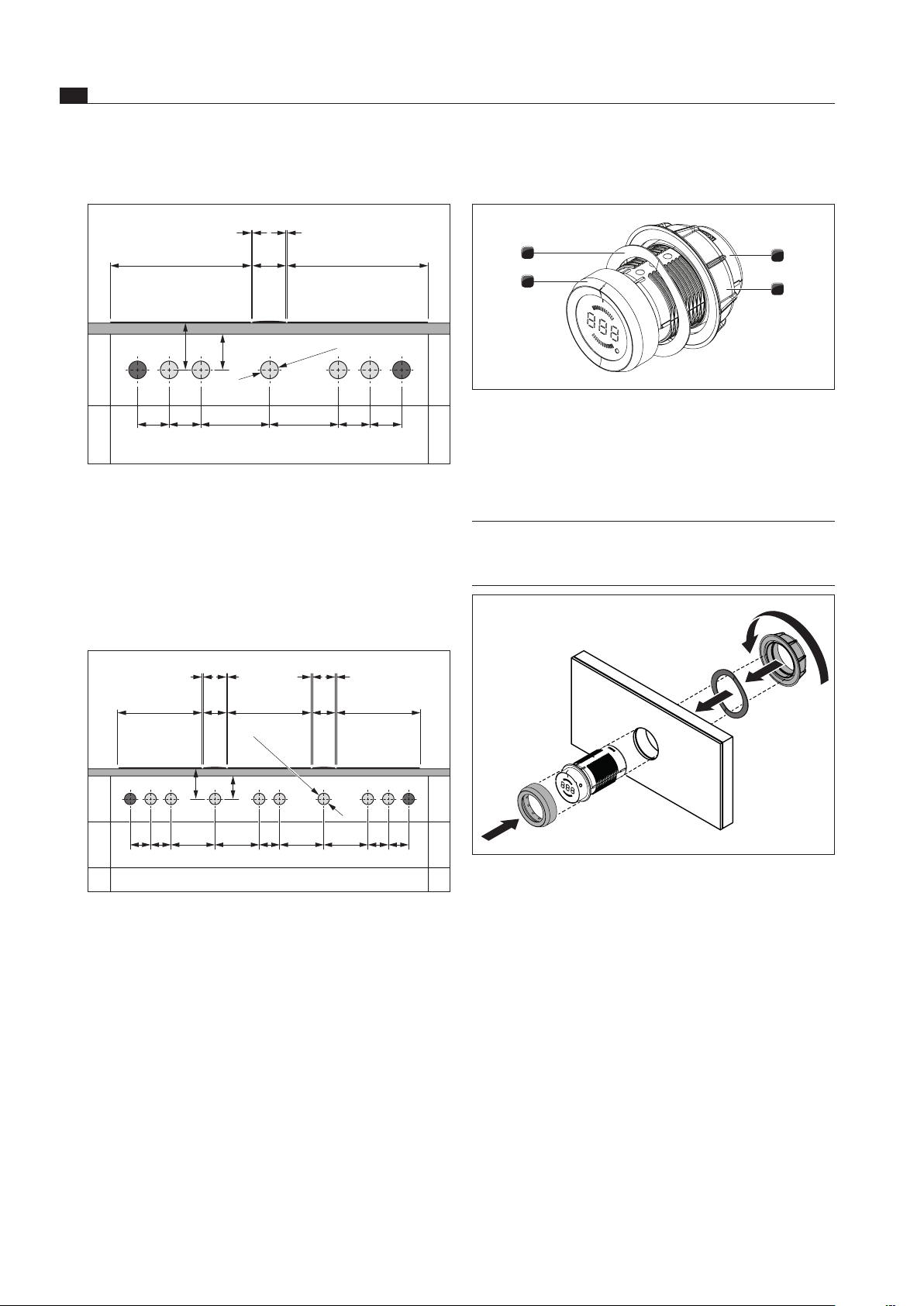
6.6.2 Fitting the control knob
3
4
2
1
Fig. 6.22 Structure of control knob
[1] Knob casing
[2] Universal nut
[3] knob ring
[4] Wave spring
INFO The wave spring must not be used with steel
fronts. The relevant assembly steps should simply
be skipped.
Fig. 6.23 Fitting the control knob
Example bore holes
≥40≥70
90 90 90
Ø50 ±0,5
90 196 196
370 370
110
1 1
Fig. 6.20 Bore holes for 2 cooktops, 2 sockets and 1 cooktop
extractor
[1] Bore holes for socket (2x external)
[2] Bore holes for control knobs (5x)
[3] Cooktop 2x
[4] Cooktop extractor
[5] Worktop
[6] Cover for the floor unit
≥70 ≥40
90 90 909090 196 196 196 196
370 370
370
110
1 1 1 1
110
Ø50 ±0,5
Fig. 6.21 Bore holes for 3 cooktops, 2 sockets and 2 cooktop
extractors
[1] Bore holes for socket (2x external)
[2] Bore holes for control knobs (8x)
[3] Cooktop 3x
[4] Cooktop extractor (2x)
[5] Worktop
[6] Cover for the floor unit
EN
23
Installation
www.bora.com
6.7.1 Airflow straight to the side
INFO For straight airflow to the side, the installation
must be rotated around 180°. This means the
cover frame also needs to be rotated (see rotating
the cover frame around 180°).
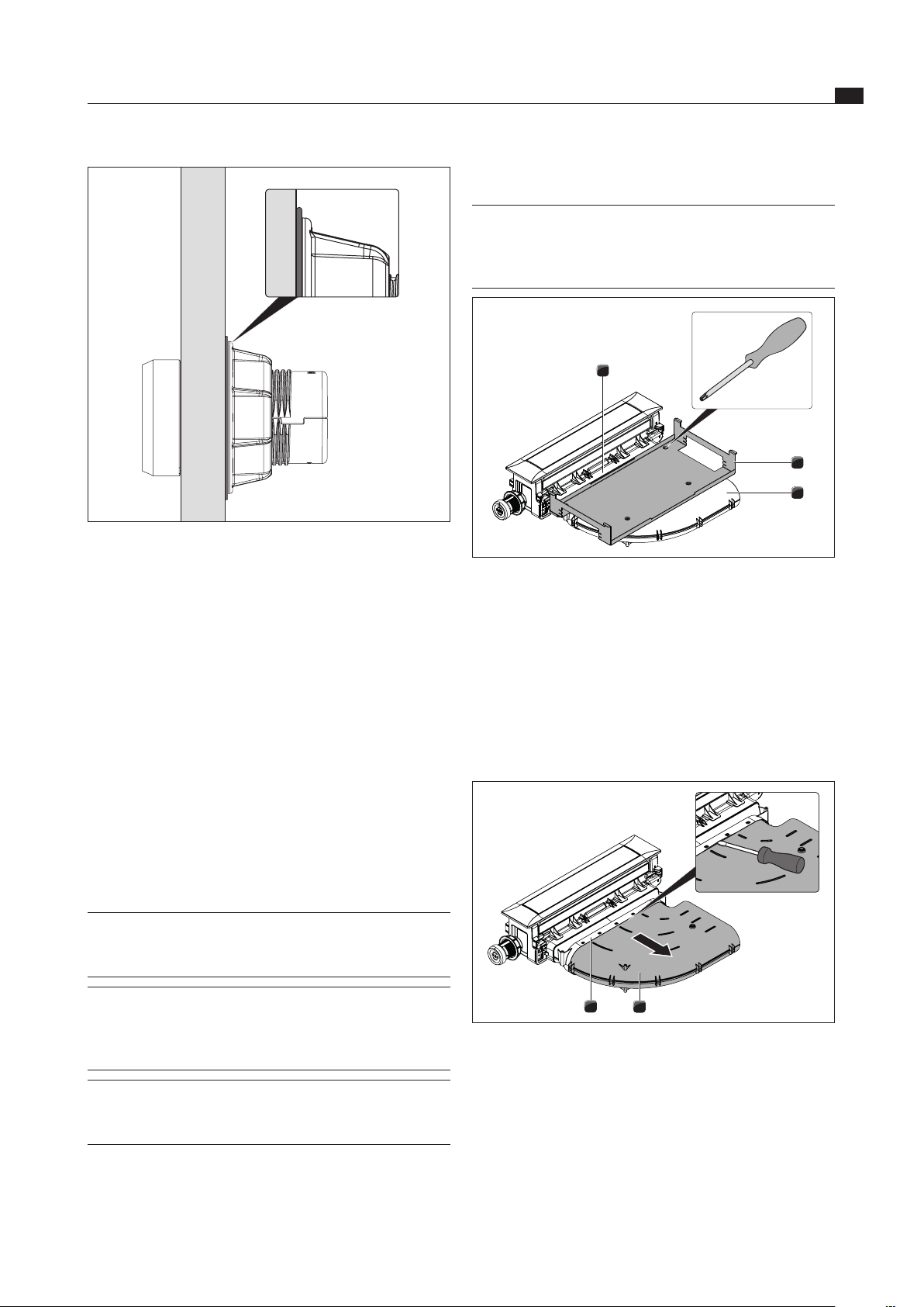
3
2
1
Fig. 6.25 Remove the holding plate
[1] Ducting piece adapter
[2] Holding plate
[3] Bent ducting piece
Undo the Torx screw (size 10) securing the holding
plate [2] to the angled ducting piece [3].
Undo the 2 Torx screws (size 10) securing the holding
plate [2] to the ducting piece adapter [1].
Remove the holding plate [2].
2
1
Fig. 6.26 Remove the angled ducting piece
[1] Angled ducting piece
[2] Ducting piece adapter
Release the angled ducting piece [1] from the ducting
piece adapter [2].
To do this, carefully disconnect the plug connection
using a flat screwdriver.
Remove the angled ducting piece [1].
If necessary, rotate the cover frame around 180° (see
Rotating the cover frame around 180°).
Fig. 6.24 Wave spring once assembly is complete
Pull off the knob ring [3].
Unscrew the universal nut [2].
Pull off the wave spring [4].
Push the knob casing [1] through the hole in the panel
from the front.
Push the wave spring [4] onto the knob casing [1] from
the rear (not with steel fronts).
Screw the universal nut [2] onto the knob casing [1]
from the rear and tighten a little.
Use the marking to align the knob casing [1] vertically
in the 12 o’clock position.
Tighten the universal nut [2].
The wave spring (if used) must be pressed flat.
Slot the knob ring [3] onto the knob casing [1] and
align it to the 12 o’clock position.
6.7 PKA planning options
INFO With the PKA cooktop extractor, you have the
option of configuring the airflow either to the left
or the right to suit your requirements.
INFO The pre-fitted angled ducting piece or straight
ducting piece (supplied) can feed the airflow
either in a 90° angle to the rear or straight out to
the side.
INFO If using the straight ducting piece, an
additional EFD straight duct seal is required (not
supplied).
The cooktop extractor is supplied with a pre-fitted
angled ducting piece going to the right.
EN
24
Installation
www.bora.com
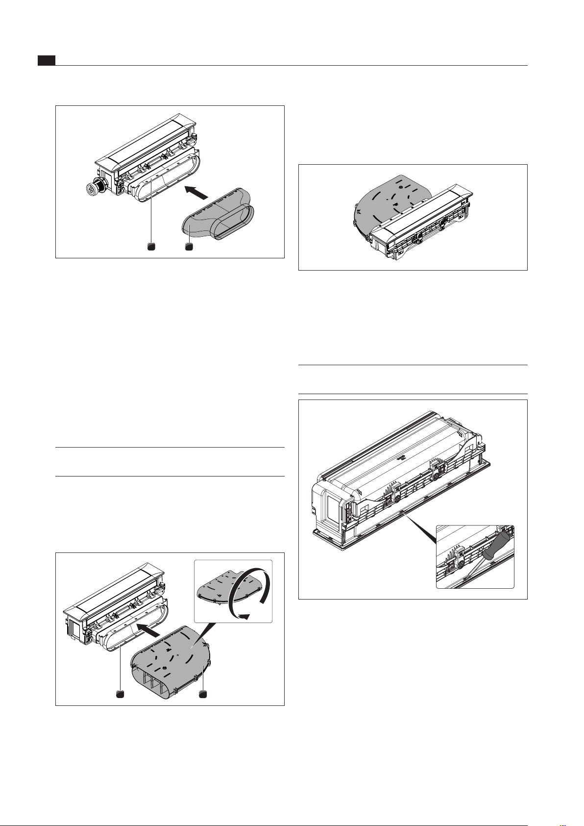
Turn the angled ducting piece [1].
Push the rotated angled ducting piece [1] back onto
the ducting piece adapter [2] until the fastening lugs
click into place.
Fig. 6.29 Airow to the left with angled ducting piece
Make sure that no air gap has formed between the
components.
Secure the holding plate.
Rotate the cover frame about 180°.
INFO In order to correct the direction of the cover
frame, it may need to be rotated around 180°.
Fig. 6.30 Dismounting the cover frame
Rotate the cooktop extractor and place it down
carefully with the visible surface on a soft surface
(e.g. a blanket).
Carefully undo the holding clamps (18x) with a
screwdriver.
2
1
Fig. 6.27 Mounting the straight ducting piece
[1] Straight ducting piece
[2] Ducting piece adapter
Push the straight ducting piece [1] onto the ducting
piece adapter [2] until the fastening lugs click into
place.
Make sure that no air gap has formed between the
components.
Secure the holding plate to the ducting piece adapter
[2] with just 2 screws.
6.7.2 Airflow to left
(installation rotated around 180°)
INFO The PKA cooktop extractor can be fitted rotated
around 180° so that the airflow is to the left.
Airflow to the left with angled ducting piece
Dismount the holding plate and the angled ducting
piece (see Airflow straight to the side).
Rotate the cover frame around 180°
(see Rotating the cover frame around 180°).
2
1
Fig. 6.28 Turn angled ducting piece
[1] Angled ducting piece
[2] Ducting piece adapter
EN
26
Installation
www.bora.com
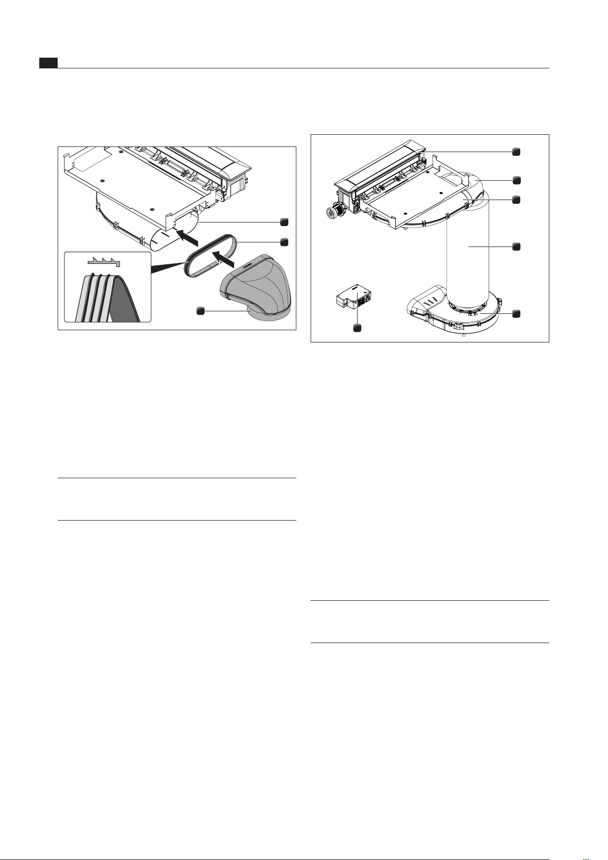
6.8.3 Standard setup PKA
1
2
3
4
5
6
Fig. 6.35 Standard setup PKA
[1] Cooktop extractor
[2] 90° diverter
[3] Bent ducting piece
[4] Silencer
[5] Universal plinth fan
[6] Universal control unit
Push the 90° diverter [2] onto the angled ducting piece
[3].
Position the plinth fan [5].
To facilitate positioning, the inlet nozzle on the plinth fan
can be removed. To do this, please see the assembly
instructions for the ULS universal plinth fan.
Connect the silencer [4] to the plinth fan [5].
Connect the silencer [4] to the 90° diverter [2].
There is also the option of gluing the connections
between the ducting sections and the plinth fan with
UDB sealing tape.
INFO Position the plinth fan and the universal control
unit in such a way that they are easily accessible
and removable for maintenance work.
The maximum exhaust air duct length with a fan is 6 m.
The minimum cross-section of the air ducts must
be 176 cm², which equates to a round pipe with
a diameter of 150 mm or the BORA Ecotube duct
system.
For the ducting, only use stable duct elements with
smooth pipe interiors. Do not use flexible or fabric
tubes.
6.8.2 Connect the duct system to the
device.
2
2
3
1
Fig. 6.34 Connecting to the duct system.
[1] Output nozzles
[2] Seal
[3] Ducting piece
Pull out the seal [2] on the connection fitting [1] of the
device. This means stretching the seal [2] slightly.
Push the duct piece [3] to be connected with the
sleeve on the connection fitting [1] with the seal [2].
Make sure the seal [2] does not move.
INFO When fitting the seal, make sure it fits and forms
an air-tight seal with the connection duct piece
when compressed.
EN
27
Installation
www.bora.com
6.10 Connecting external switch
contacts
INFO The Home In and Home Out communication
connections must only be connected by a
certified specialist. The specialist also assumes
responsibility for the proper installation and
commissioning.
When using Home In and Home Out, you will require the
relevant documents for the external switch devices in
order to ensure safe device connection and operation.
The following switch contacts can be used:
Contact Function Connection
Home In Cooktop extractor on/off connection
for external switch contact (contact
closed: cooktop extractor on)
24V DC
100 mA
Home Out Electrically isolated contact for
controlling external installations
depending on the operating
status of the cooktop extractor
(cooktop extractor on: contact closed)
maximum
250 VAC
/ 30 VDC,
2,5A
Tab. 6.5 Switch contacts
INFO The Home In contact can be used for external
safety devices (e.g. window contact switches). If
the switch is open, the cooktop extractor is out of
operation.
Make sure that the universal control unit is
disconnected from the power supply.
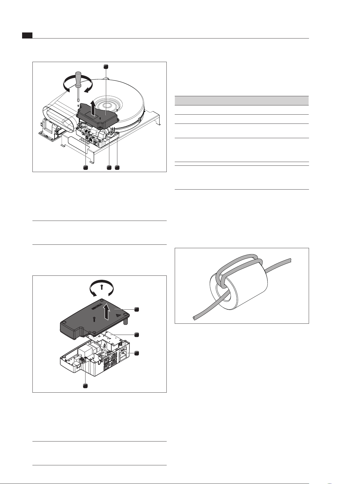
PKAS and PKASAB preparation
INFO To ensure that the surface of the device does
not get scratched when the cooktop extractor
system is rotated, a surface must be used that will
protect the device (e.g. cardboard).
Place a soft layer on the surface.
Rotate the cooktop extractor system and place it with
the top of the top side of the device on the soft layer.
Undo the screws on the control unit on the bottom of
your cooktop extractor system.
Lift up the cover [1].
6.8.4 Installing the additional fan
Install the additional fan in the exhaust duct.
Ensure that a minimum clearance of 3 m is maintained
between the fan units.
Only use BORA universal fans with your BORA cooktop
extractor system.
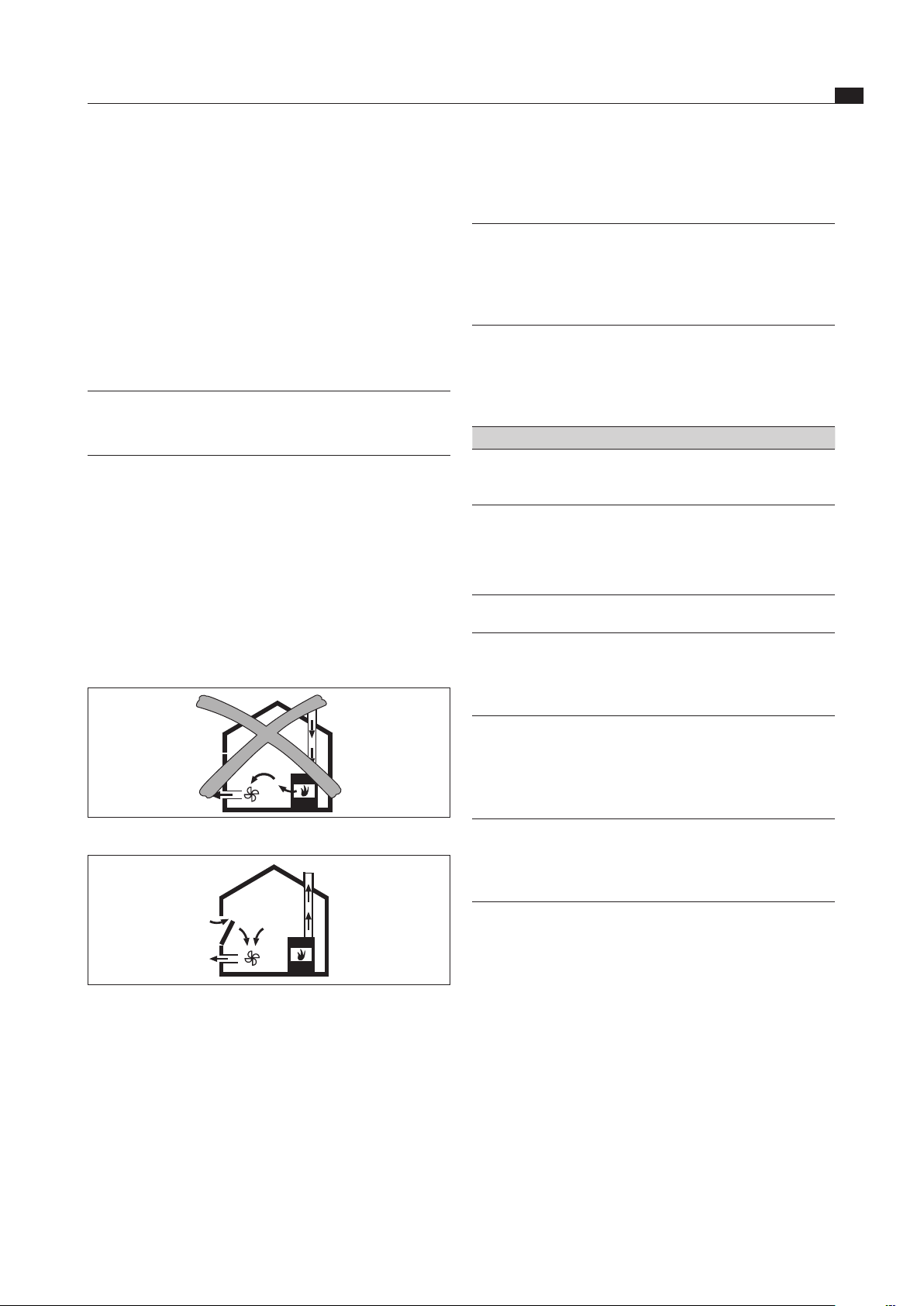
6.9 Operating the cooktop extractor
with a fireplace that depends on
the air in the room
INFO The state and regional laws and regulations must
be observed with regard to the exhaust duct
design. A sufficient air supply must be ensured.
Fireplaces that depend on the air in the room (e.g. gas,
oil, wood or coal-fired heaters, continuous-flow water
heaters, instantaneous water heaters) draw in air from
the room in which they are installed and release the
exhaust fumes into the outside air via an exhaust system
(e.g. chimney).
If the cooktop extractor is used in exhaust mode, it draws
in air from the room in which it is installed as well as from
neighbouring rooms. If there is insufficient air supply, low
pressure will occur. Toxic gases could be drawn out of the
chimney or extraction ducting and back into the room.
Fig. 6.36 Exhaust air installation – not permitted
Fig. 6.37 Exhaust air installation – correct
If simultaneously operating both a fireplace and the
cooktop extractor in the same room, ensure that:
the maximum low pressure is 4 Pa (4 x 10⁻⁵ bar);
a safety device (e.g. window contact switch, low
pressure warning device) is used to ensure that a
sufficient supply of fresh air is guaranteed;
the exhaust air is not be ducted into a chimney that
is used for exhaust gases of devices operated with
gas or other combustibles;
the installation is checked and approved by an
authorised certified engineer (e.g. heating engineer).
EN
28
Installation
www.bora.com
Preparing connection cables for external
switching equipment
Use connection cables of the following types and
manufacturers to connect external switchgear.
Contact Connection cable
Home In H03VV-F 2 x 0.5 mm²
Home Out H03VVH2-F 2 x 0.75 mm²
Tab. 6.6 Connection cable
INFO The connection cable is only intended for internal
use in buildings, private households, kitchens or
offices.
INFO The overall length of the connection cable for
external switching equipment must not exceed
10 m!
For reasons of electromagnetic compatibility, all
connection cables from external switch devices must be
filtered with a ferrite sleeve. This is not included in the
scope of delivery.
Use the order code UFH (universal filter sleeve) to
order the filter sleeve from your specialist supplier or
contact BORA via the website at www.bora.com.
Fig. 6.40 Wrap the connection cable round the ferrite sleeve
three times
Wrap the connection cable around the ferrite sleeve
3 times to create the desired filter performance.
Ensure that the cable end protrudes at least 120 mm
from the sleeve.
Prepare the connection cable in accordance with the
prescribed stripping lengths.
4 3 2
1
Fig. 6.38 Open the cover of the control unit
[1] Cover
[2] Housing
[3] Electronic unit
[4] Switch contact terminals
INFO The electronic unit [3] can contain residual
charge. You must therefore be careful not to
touch the exposed contacts on the electronic unit!
PKA preparation
Remove the screws from the universal control unit.
Lift up the cover [1].
1
2
4
3
Fig. 6.39 Open the universal control unit’s cover
[1] Cover
[2] Electronic unit
[3] Base unit
[4] Switch contact terminals
INFO The electronic unit [2] can contain residual
charge. You must therefore be careful not to
touch the exposed contacts on the electronic unit!
EN
29
Installation
www.bora.com
INFO The Home In contact must be bridged if this is not
used (bridged on delivery).
For connections to the Home In connection clamp, no
ferrules may be used.
Clamp the connection cable in the strain relief clamp
[4] in accordance with the wire cross section used.
INFO If external switching devices are connected both
to the Home In and Home Out interfaces, both
cables should be secured with the strain relief
claim [4].
Remove the relevant snap-out element [2] in the
plastic housing of the universal control unit.
1
2
Fig. 6.43 Home Out contacts with strain relief
[1] Strain relief clamp
[2] Snap-out element for cable feed
Check the correct installation, as well as the firm
positioning of the connection cables.
Close the cover on the universal control unit.
Make sure that the cable is not damaged.
Switch on the main switch/automatic circuit breaker.
6.11 Establishing communication and
power connection
Observe all safety and warning information (see the
Safety section).
Observe all national and regional laws and regulations
as well as the supplementary regulations of the local
utility companies.
The plug for the power supply must be accessible
following installation.
If the power supply cable has been damaged this must
be replaced.
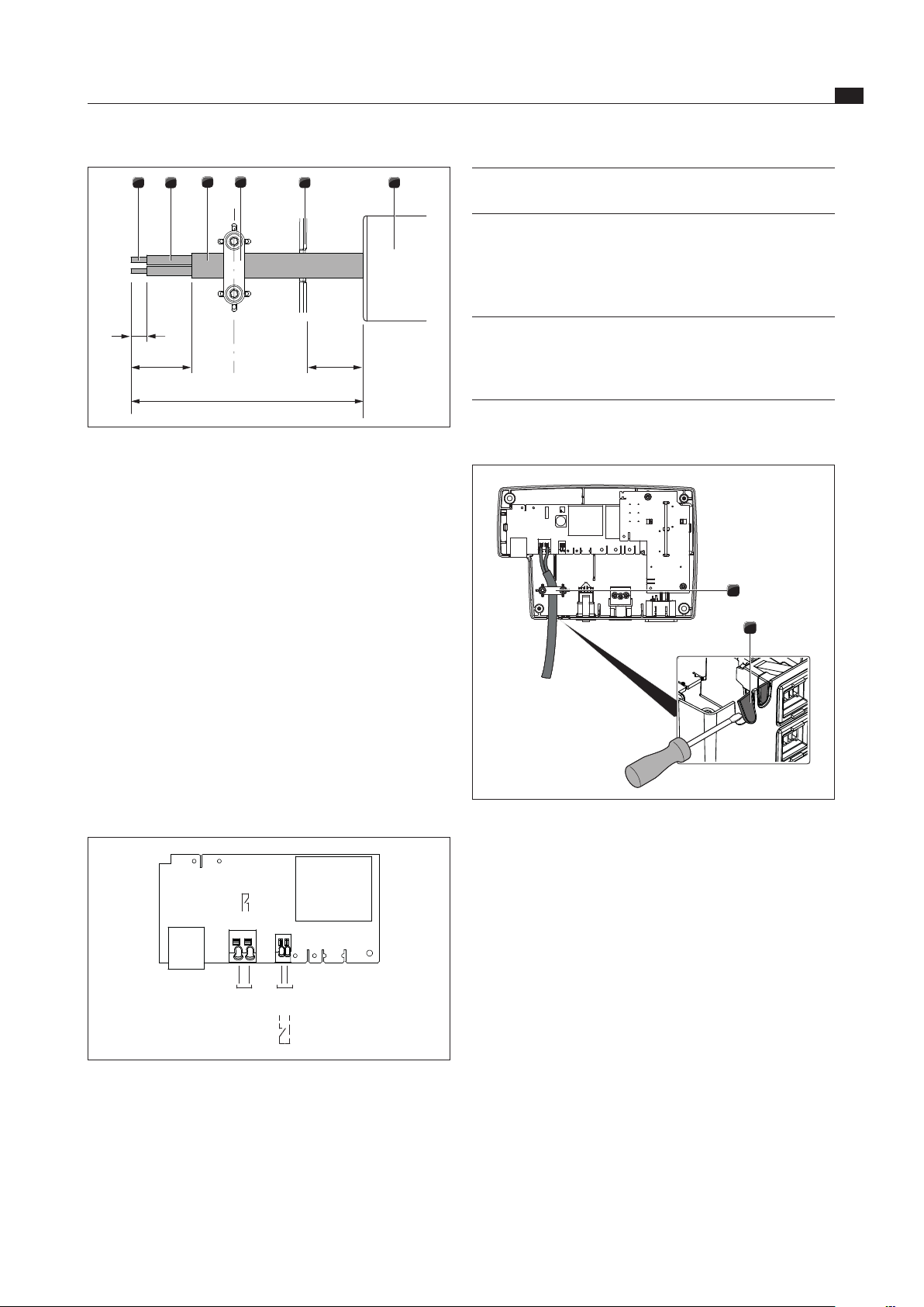
6
5
3
2
1
4
9
UFH
35
120
20
Fig. 6.41 Stripping lengths and installation position for
connection cable
[1] Stripped wire end
[2] Insulated wire
[3] Jacketed cable
[4] Strain relief clamp
[5] Cable feed snap-out element
[6] Universal ferrite sleeve (UFH)
Please adhere to the maximum stripping length of
9 mm on the stripped wire end [1].
Please adhere to the maximum stripping length of
26 mm on the insulated wire [2].
Installing the external switch device
Depending on the type of switch device, connect the
connection cables to either the Home In or the Home Out
connection clamp.
Adhere to the connection diagram when connecting
Home In and Home Out.
Home
In
Home
Out
X 7.1
X 7.2
X 6.1
X 6.2
Fig. 6.42 Connection diagram for the external switch contacts
Connect the cable for the relevant contact to the
switch contact clamp in accordance with the relevant
connection diagram (see fig. Connection diagram for
the external switch contacts).
In order to connect the Home In interface, the installed
bridge must be removed.
EN
30
Installation
www.bora.com
6.11.2 PKAS and PKASAB connections
Fig. 6.46 PKAS and PKASAB rear connections
[1] Home In
[2] Home Out
[3] Control line for additional fan
[4] Mains connection cable for additional fan
[5] Power supply cable with microfuse
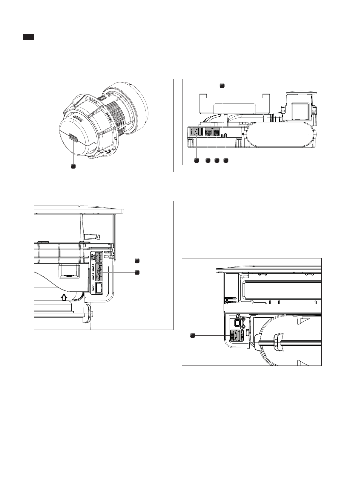
6.11.3 PKA connection
Connecting the universal control unit and fan
to the cooktop extractor
1
Fig. 6.47 Side connection for control unit on cooktop extractor
PKA
[1] Control unit connection
6.11.1 Connecting the control knob
1
Fig. 6.44 Back of control knob with connection
[1] Control knob connection
2
1
Fig. 6.45 Side connections on cooktop extractor
[1] Connection the control knob
[2] Connection for cooktops
Connect the control knob connection to the side
connection on the cooktop extractor [1].
Use the ribbon cable provided.
2345
1
EN
31
Installation
www.bora.com
Release the power supply cable
To release the power supply cable for the fan [1] from
the universal control unit [6] you need a small flat
screwdriver.
Disconnect the universal control unit’s power supply
cable from the power supply [8].
Make sure that there is no power to the appliance.
Use the flat screwdriver to loosen the lock on the fan
power supply cable plug.
To do this, insert the flat screwdriver into the gap in
the socket.
Press the lock down gently.
Use the flat screwdriver to gently lever the plug of the
power supply cable out of the universal control unit’s
socket.
Now disconnect the power supply cable from the
socket.
Check the plug and the socket for damage.
Do not use damaged components.
Contact your BORA specialist supplier to replace any
damaged components.
Connecting the additional fan
Connect the fan control line [2] to the universal control
unit [5].
Connect the fan mains connection line [1] to the
universal control unit [7].
Check all the plug connections to ensure that they are
secure.
6.11.4 Establishing the power connection
Connect the mains connection line for the extraction
system (PKAS, PKASAB) or the mains connection
cable for the universal control unit (PKA) to the power
supply.
Put the cooktop extractor into operation
(see the Operation section).
Check that all the functions are working correctly.
6.12 Configuration menu
Once installation is complete, you must configure
certain basic settings for your cooktop extractor (see
also the supplementary information sheet on initial
commissioning).
6.12.1 Accessing the configuration menu
Turn the knob ring from the 12 o-clock position to the
11 o’clock position.
A0 appears in the control knob display.
Now press the touch surface for 5 seconds.
This accesses the configuration menu and
C
is shown
on the control knob display.
86
4
2
1
75
3
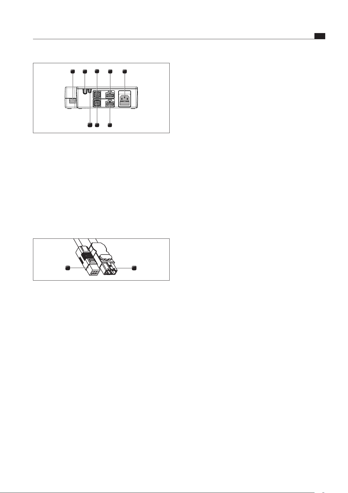
Fig. 6.48 Connections on the universal control unit
[1] CAT 5 communication cable
[2] Home Out
[3] Home In
[4] Fan 1 control line
[5] Fan 2 control line
[6] Fan 1 power supply cable
[7] Fan 2 power supply cable
[8] Power supply cable with microfuse
Use the CAT 5 communication cable to connect the
connection for the control unit on the cooktop extractor
to the connection on the universal control unit [1].
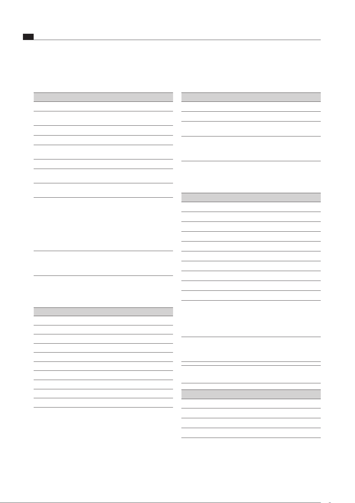
2
1
Fig. 6.49 Connection plug of the plinth fan
[1] Connection plug of the plinth fan power supply cable
[2] Connection plug of the plinth fan control line
Connect the plinth fan’s control line [2] to the universal
control unit.
Connect the plinth fan’s power supply cable [1] to the
universal control unit .
EN
32
Installation
www.bora.com
Select mode
When you have confirmed menu option
C 1
, you can select
the operating mode.
Setting Mode
C 10
Normal operating mode Factory setting
C 1 1
Demo mode
Tab. 6.9 Operating modes
INFO
In demo mode, all the control knob functions are
active and the electric cover flap and the fan work.
Demo mode is used, for example, for exhibitions.
Adjust the speed of the cover flap motor
You can adjust the speed of the cover flap motor under
menu option
C2
.
Setting
Speed of cover flap
C20
100% (fastest)
C2 1
10% (slowest)
C22
20%
C23
30%
C24
40%
C25
50%
C26
60% Factory setting
C27
70%
C28
80%
C29
90%
Tab. 6.10 Speed of cover ap
Selecting the filter unit
You can select the filter unit installed under menu option
C3
.
INFO Selecting correctly is key to ensure the filter timer
is set to the service life of the activated charcoal
filter (recirculation mode only).
INFO In the event of a power cut, the last setting saved
is shown for 2 minutes.
Setting Filter system Service life
C30
Exhaust air No filter timer required
C3 1
ULB1 200 h
C32
ULB3 (factory setting) 400 h
C33
ULBF 300 h
Tab. 6.11 Selecting the lter unit
6.12.2 Select menu option
Turn the knob ring to select the menu option you want.
The following menu options are available:
Display Menu option
C0
Volume of warning beep
C 1
Select operating mode
(demo mode)
C2
Speed of cover flap motors
C3
Selection of filter unit
C4
Exhaust air and/or recirculation
(summer or winter mode)
No current function
C5
Operation with/without wall sleeve
C6
Manual operation of cover flap
motors
C7
Switchover of PWM values for
PKA/PKAS, PKASAB fan
for BORA Service
Technicians only
Tab. 6.7 Menu options in the conguration menu
Touch the touch surface on the control knob again for
1 second to confirm the menu you want.
The sub-menu is accessed and the display switches to
a three-character combination (e.g.
C23
).
INFO In the three-character combination shown, the
right-hand figure shows the value saved in the
system.
Setting the volume of the warning beep
Once you have confirmed menu option
C0
, you can set
the volume of the warning beep.
Setting Warning beep volume
C 00
100% (max. volume) Factory setting
C0 1
10% (min. volume)
C 02
20%
C 03
30%
C 04
40%
C 05
50%
C 06
60%
C 07
70%
C 08
80%
C 09
90%
Tab. 6.8 Warning beep volume
EN
33
Installation
www.bora.com
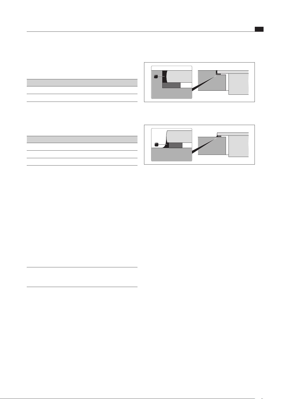
6.13 Sealing the devices
1
Fig. 6.50 Silicone sealant for ush installation
[1] black, heat-resistant silicone sealant
1
Fig. 6.51 Silicone sealant for surface mounting
[1] black, heat-resistant silicone sealant
Once all of the installation work and initial operation is
complete, seal the devices all around with black, heat-
resistant silicone sealant (also between the cooktop
extractor and cooktop) [1].
Make sure that no silicone sealant gets under the
cooktop.
6.14 Handover to user
Once installation is complete:
Explain the main functions to the user.
Explain all safety-related aspects of operation and
handling to the user.
Provide the user with the accessories and the
operating and installation instructions for safe storage.
Operation with/without wall sleeve
In the
C5
menu option, you can select whether the
extraction system is operated with or without the
BORA 3box (UEBF) wall sleeve.
Setting Mode
C50
Operation with wall sleeve
C5 1
Operation without wall sleeve
Tab. 6.12 Operation with or without wall sleeve
Manual operation of cover flap motors
You can open or close the cover flap manually in the
menu option
C6
.
Setting Function
C60
Exit sub-menu
C6 1
Opening the cover flap
C62
Closing the cover flap
Tab. 6.13 Manual operation of cover ap motors
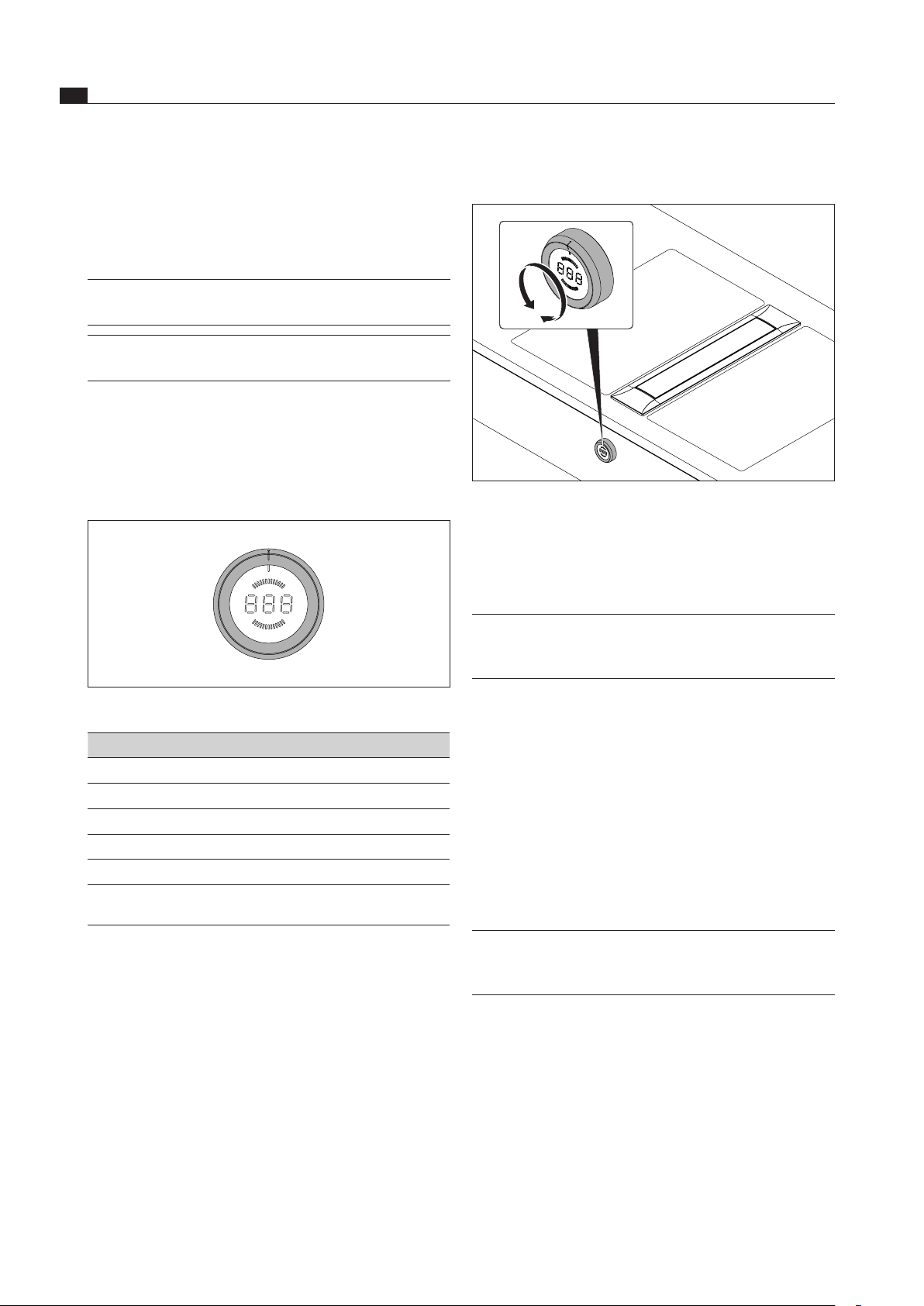
6.12.3 Changing the setting
Turn the knob ring clockwise to increase the value.
Turn the knob ring anticlockwise to decrease the value.
Press the touch surface on the control knob again for
1 second to confirm the new setting. The value is saved
and a beep sounds. The previously selected menu
option is shown again on the control knob display.
6.12.4 Exiting configuration menu
Twist the knob ring until the display shows
C
.
Now press the touch surface on the control knob again
for 1 second to exit the configuration menu.
Twist the knob ring to the 12 o’clock position.
0
appears on the display for 10 seconds. The display
then goes out with a beep.
INFO If no settings are changed in a menu or sub-menu
option for 2 minutes, the configuration menu is
closed automatically.
EN
34
Operation
www.bora.com
7 Operation
Observe all safety and warning information during
operation (see the Safety section).
INFO The cooktop extractor must only be operated with
BORA cooktops.
INFO The cooktop extractor can only be operated if the
grease filter components are installed.
7.1 General operating instructions
The cooktop extractor is controlled using the control knob.
There are 9 power levels, 1 power setting and various
functions available:
A0 / C
P
9
8
7
6
5
4
3
2
1
c
0
Fig. 7.1 Knob ring assignment
Knob ring position Function
0
Fan off
c
Cleaning position
1 - 9
Power levels
P
Power setting
A0
Automatic cooktop extractor function
C
Configuration menu (see the Installation
section)
Tab. 7.1 Knob ring positions
7.2 Operating the cooktop extractor
Recommendations for efficient vapour extraction
Always use a lid on pots that are particularly high. This
ensures effective vapour extraction. It also reduces
power consumption.
Only operate the cooktop extractor at the minimum
power level required for effective vapour extraction.
This enables you to improve the performance of the
odour filters in recirculation mode.
Only operate the hob at the minimum power level
required for cooking. This reduces the cooking vapours
and the power consumption.
Avoid strong drafts.
7.2.1 Switching on the cooktop extractor
Fig. 7.2 Switching on the cooktop extractor
Turn the knob ring from the 12 o-clock position to
the power level you want. The knob clicks in at the
different levels.
Avoid undefined interim positions.
INFO If the control knob ring is turned to an undefined
interim setting, the most recently selected power
level is automatically activated.
Adjusting the power level
Turn the knob ring to the desired power level.
The power level selected is shown in the power display
on the control knob.
Set power setting
Twist the knob ring to the 10 o’clock position.
The cooktop extractor will run for a maximum of
9 minutes on the power setting. P is displayed on the
power display on the control knob.
7.2.2 Automatic cooktop extractor function
INFO The extraction power is generally adjusted
30 seconds after the power level is set on the
cooktop.
Twist the knob ring to the 11 o’clock position.
If now power level is yet set on one of the cooktops
connected,
A0
is shown on the control knob display.
If, for example, one of the cooktops connected is set
to power level
7
, then the display changes to
A7
and
the extraction power is automatically adjusted with a
30 second delay.
If all the cooking zones connected are switched off or
temporarily stopped, the automatic after-run starts.
Deactivate automatic cooktop extractor function:
turn the knob ring to a power level, the power setting
or the 12 o-clock position.
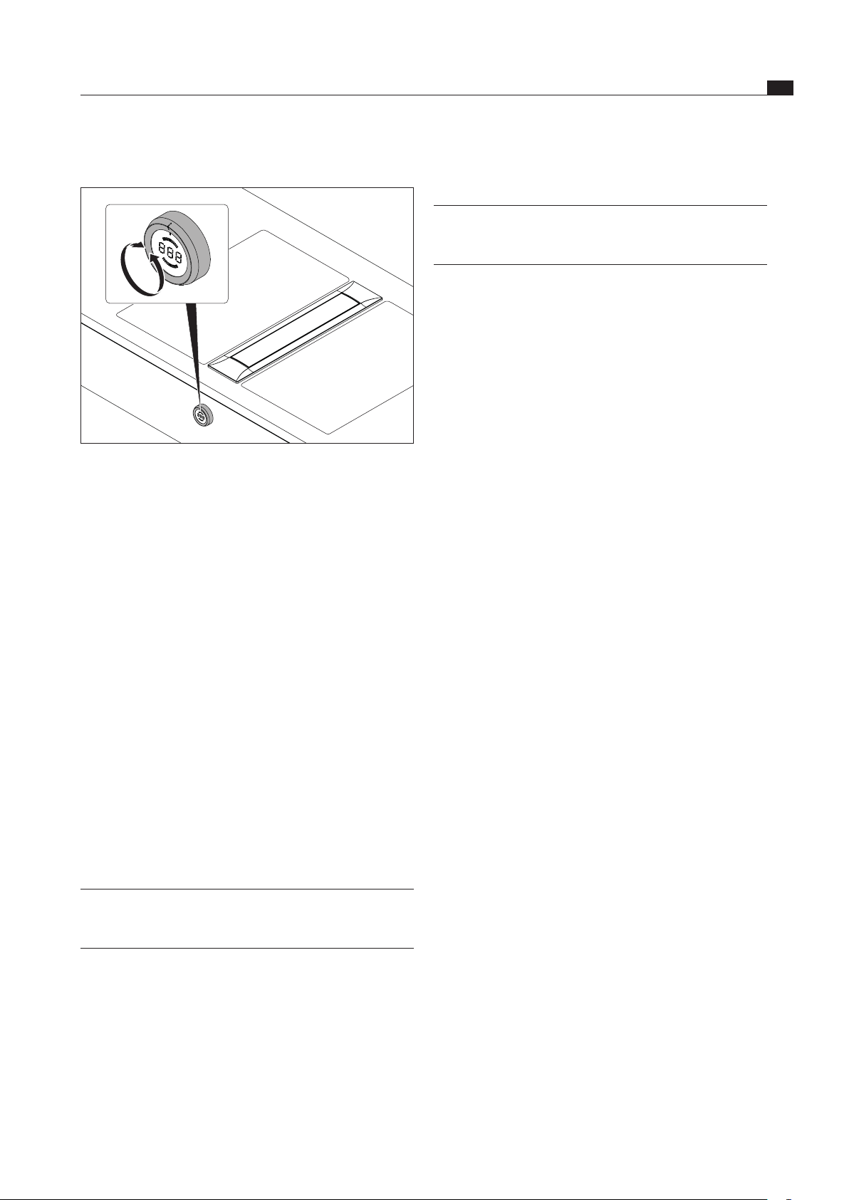
EN
35
Operation
www.bora.com
Permanently deactivating the childproofing
feature
INFO The childproofing feature can only be permanently
deactivated if the knob ring is in the 12 o’clock
position.
Press the touch surface of the control knob for
5 seconds.
An acoustic signal can be heard and the display on the
control knob switches to
L
. After 10 seconds, another
acoustic signal sounds and the display goes out. The
childproofing feature is deactivated.
Deactivating the childproofing feature for a
cooking session
Turn the knob ring from the 12 o-clock position to a
power level.
L
appears in the control knob display.
Press the touch surface of the control knob for
5 seconds.
An acoustic signal can be heard and the control knob
display shows the power level selected.
The childproofing feature is only deactivated for this
cooking session and you can set the power level you
want.
The childproofing feature is reactivated next time you
switch on.
7.2.6 Crush protection
The electrical cover flap on the cooktop extractor has
crush protection.
If the cover flap is blocked while it is opening or
closing, the movement is stopped automatically.
The cover flap moves back to its starting position.
End
is displayed on the control knob.
Remove the foreign body which is in the way.
Press the touch surface for 1 second.
The cover flap is working again.
If the cover flap is blocked three times in succession
while automatically opening or closing, the appliance
will be automatically disabled for 5 minutes.
To re-activate the appliance after 5 minutes, touch the
touch-operated area for 1 second.
7.3 Note the filter service function
If a flashing
F
is shown on the control knob display after
switching on the cooktop extractor, the service life of the
activated charcoal filter is up (for recirculation only) and
the grease filter needs thorough cleaning.
7.2.3 Switching off the cooktop extractor
Fig. 7.3 Switching o the cooktop extractor
Twist the knob ring to the 12 o’clock position. The
knob ring slots into this position and the automatic
after-run starts.
7.2.4 Automatic after-run
Once the cooktop extractor is switched off, the
automatic after-run starts.
n
appears in the control
knob display.
The cooktop extractor switches off automatically after
20 minutes and the cover flap closes.
Deactivate automatic after-run early.
Press the touch surface of the control knob for a
second. An acoustic signal can be heard and the
display switches to
0
.
The cover flap closes and the display goes out after 10
seconds.
7.2.5 Childproofing feature
The cooktop extractor has a childproofing feature to
prevent accidental switching on.
Activating the childproofing feature
INFO The childproofing feature can only be activated
if the knob ring is in the 12 o’clock position and
there are no active functions.
Press the touch surface of the control knob for
5 seconds.
An acoustic signal can be heard and the display on the
control knob switches to
L
. After 10 seconds, another
acoustic signal sounds and the display goes out. The
childproofing feature is activated.

EN
36
Operation
www.bora.com
Exiting the filter service display and setting a
power level
Press the touch surface of the control knob for a
second.
The control knob display switches to the power level
selected. The fan motor starts up at the power level
selected.
Changing the filter
Switch off the cooktop extractor.
Observe all the information provided in the Cleaning
section.
Replace the activated charcoal filter.
Clean the grease filter.
Resetting the filter service display
If the activated charcoal filter has been replaced and the
grease filter has been cleaned, it will be necessary to
reset the filter service display.
Twist the control knob to the 12 o’clock position.
Within 10 seconds, press the touch surface of the
control knob for 5 seconds.
The display switches to
0
and the filter service display
is reset.
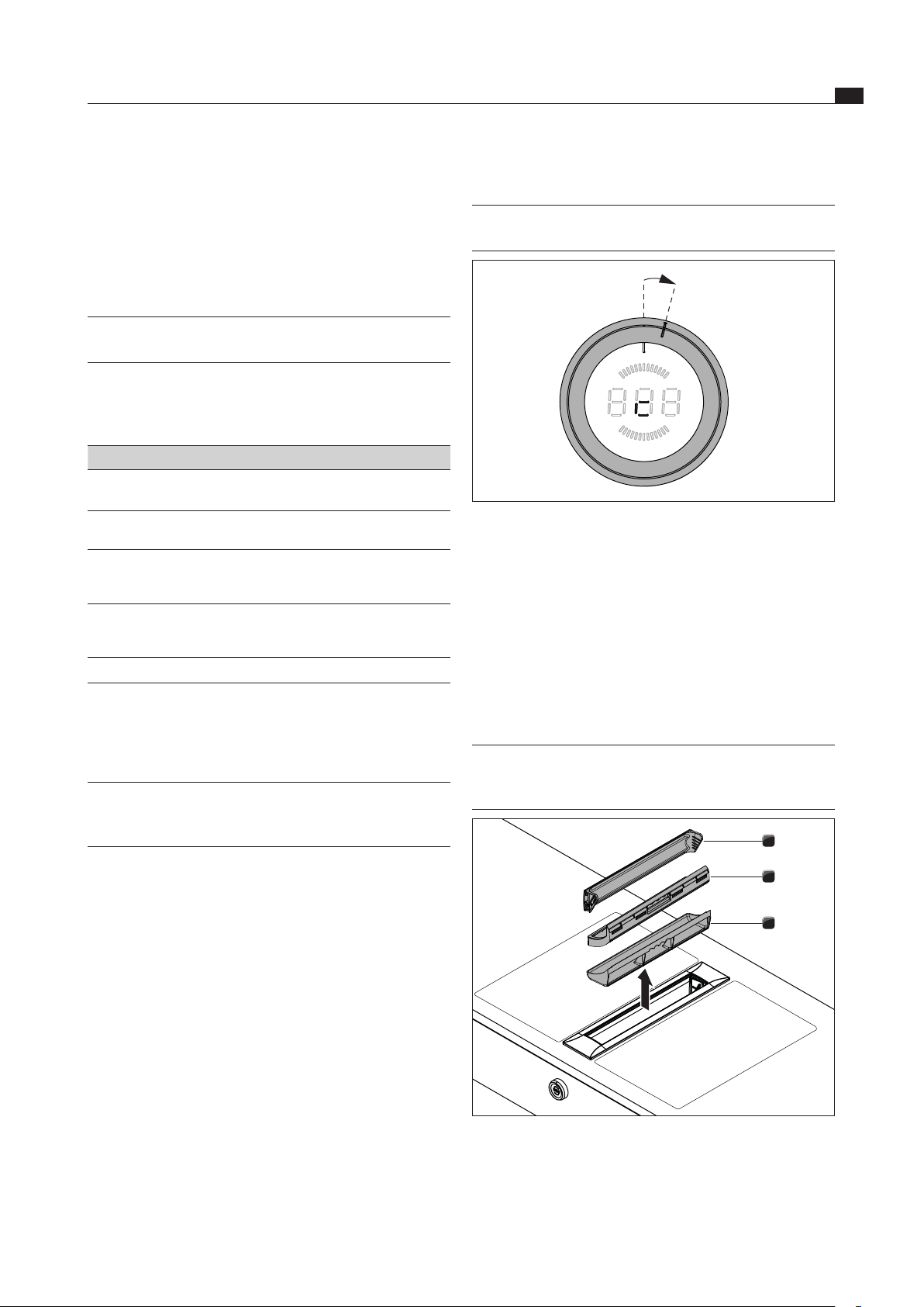
EN
37
Cleaning and maintenance
www.bora.com
8 Cleaning and
maintenance
Observe all safety and warning information
(see the Safety section).
INFO Clean the stainless steel surfaces in the polishing
direction only.
Regular cleaning and maintenance ensures the
longevity of the product and optimal function.
Adhere to the following cleaning and maintenance cycles:
Component Cleaning cycle
Cooktop extractor interior and
surface
After cooking very greasy dishes;
at least once a week
Cover flap, grease filter and
filter tray
After cooking very greasy dishes;
at least once a week
Maintenance tray as required (when the activated
charcoal filter is replaced at the
latest for recirculation mode)
Activated charcoal filter
(with recirculation only)
Replace if odours have built up or
the service life has expired
(see Filter service display)
Knob ring/Knob housing Immediately after every soiling
Tab. 8.1 Cleaning cycles
8.1 Cleaning agents
INFO Due to the use of aggressive cleaning agents and
abrasion caused by the pot bases the surface will
become damaged and dark stains will occur.
Never use steam cleaners, abrasive sponges, scouring
pads or chemically aggressive cleaning agents
(e.g. oven cleaner spray).
Make sure that the cleaning agent does not contain
any sand, soda, acids, lyes or chloride.
8.2 Cleaning the cooktop extractor
Grease particles and limescale residues from cooking
vapours can settle on the surface and in the extraction
system.
Clean the components of the cooktop extractor in
accordance with the cleaning intervals.
Remove the cover flap, grease filter and filter tray prior
to cleaning.
Clean the surfaces using a soft, damp cloth, detergent
or a mild window cleaning agent.
Soften dried on dirt using a damp cloth
(do not scrape it off!).
8.2.1 Cleaning position for cover flap
INFO The cleaning position is between the 12 o’clock
position and the 1 o’clock position.
15°
Fig. 8.1 Cleaning position
Make sure that the cooktop extractor is switched off
(see the Operation section).
Turn the selector ring approximately 15° clockwise
from the 12 o’clock position until it lightly engages.
The display shows c and the cover flap opens.
The fan motor does not run or switches itself off if it
was running.
8.2.2 Removing the cover flap, the grease
filter and the filter tray
INFO The grease filter components can only be
removed if the cover flap is in the cleaning
position.
3
2
1
Fig. 8.2 Removing the grease lter components
[1] Cover flap
[2] Grease filter
[3] Filter tray
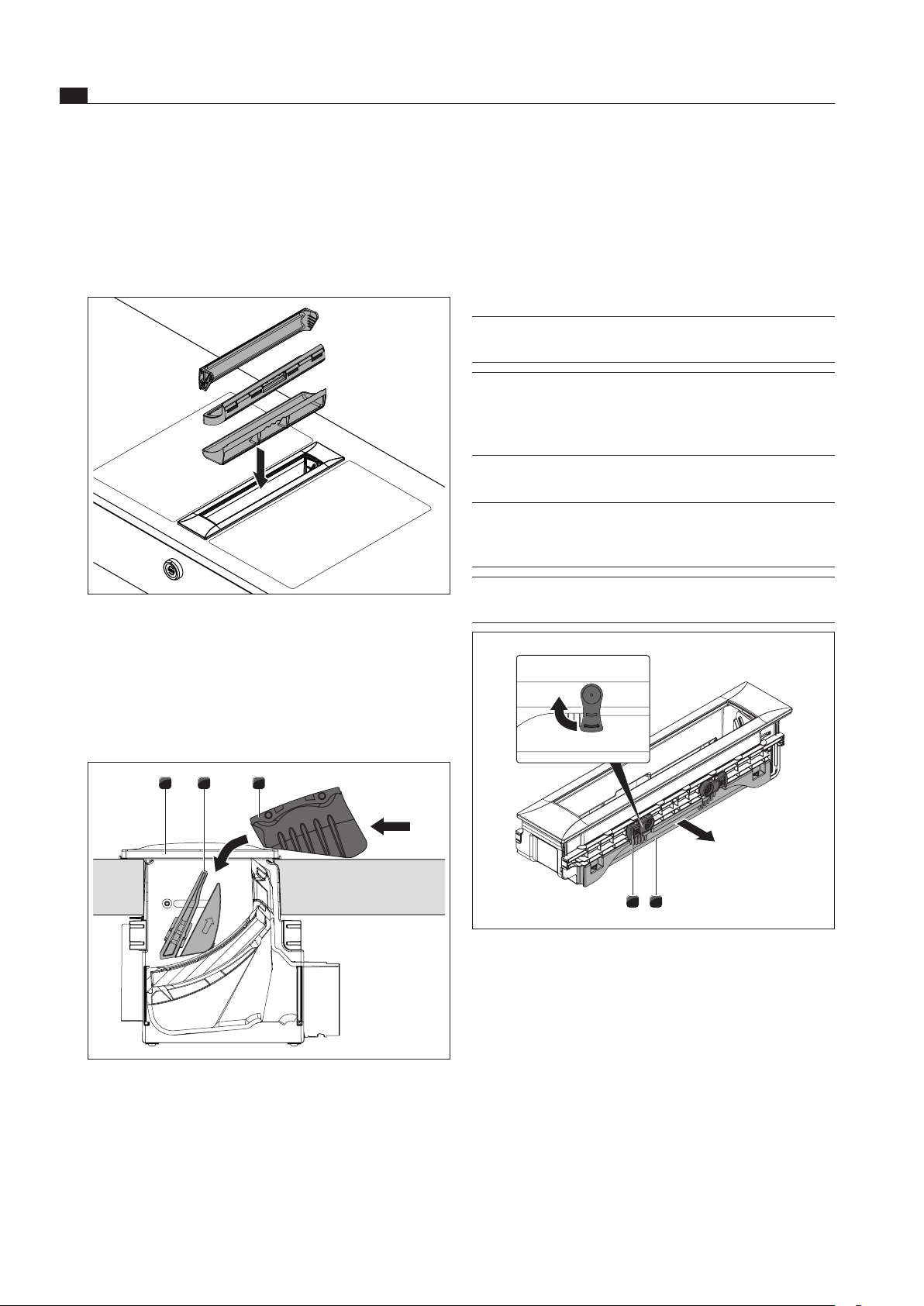
EN
38
Cleaning and maintenance
www.bora.com
Place the cover flap [3] on the side next to the exhaust
opening [1].
Allow the cover flap [3] to slide vertically into the guide
[2].
Gently press the narrow side of the cover flap [3] from
the top until you feel it slot into place.
Make sure the cover flap [3] is correctly fitted.
INFO If the cover flap is not fully in the slot after fitting,
it cannot be closed properly.
INFO If the grease filter or the cover flap have not been
properly fitted, error message E0 12 or E0 13
appears on the control knob display
(see Troubleshooting section).
8.2.4 Removing the maintenance tray
INFO The maintenance tray cannot be removed in the
following installation scenarios. Single installation,
adjacent 2nd extractor, adjacent wok cooktop.
INFO To remove the maintenance tray, the grease filter
and the filter tray must first be removed.
2 1
Fig. 8.5 Removing the maintenance tray
[1] Maintenance tray
[2] Locking
To unlock the maintenance tray [1], twist the two
locking levers [2] 90° outwards.
Remove the maintenance tray [1] from the cooktop
extractor.
Lift the cover flap [1] off upwards.
Reach into the opening in the cooktop extractor and
remove the grease filter [2] and the filter tray [3].
8.2.3 Fitting the cover flap, the grease filter
and the filter tray
Fig. 8.3 Fitting the components
Fit the filter tray into the exhaust opening.
Insert the grease filter into the exhaust opening.
Make sure the grease filter sits correctly in the opening
in the casing.
Inserting the cover flap:
1 2 3
Fig. 8.4 Inserting the cover ap
[1] Exhaust opening
[2] Guided tour
[3] Cover flap
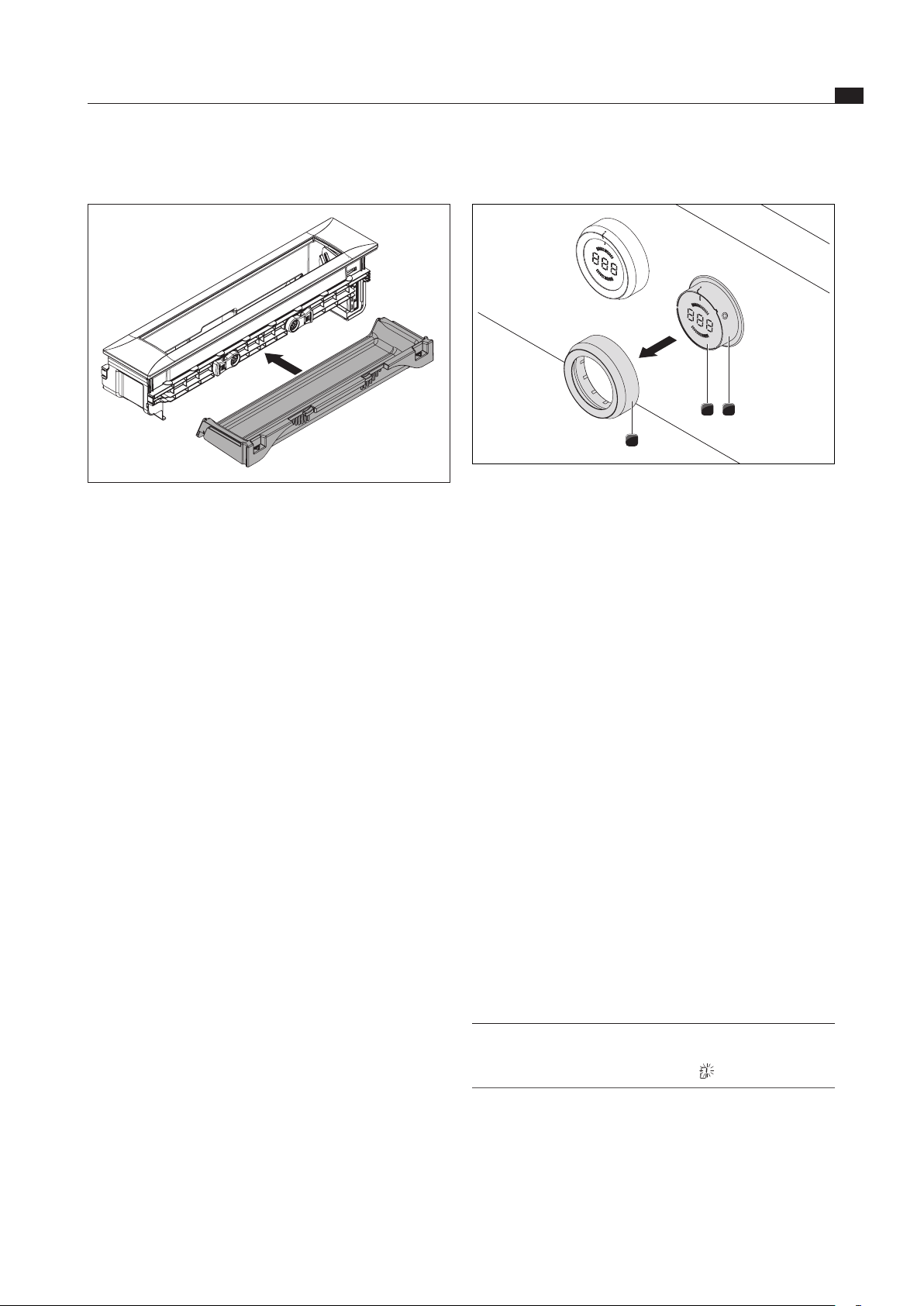
EN
39
Cleaning and maintenance
www.bora.com
8.3 Cleaning the control knobs
12
3
Fig. 8.7 Pull out the knob ring
[1] Knob casing
[2] Touch surface
[3] knob ring
Make sure that the cooktop extractor is switched off
(see the Operation section).
8.3.1 Cleaning the knob ring
The knob ring can only be cleaned by hand.
Remove the knob ring from the knob housing.
Use a cleaner and degreaser in one.
Rinse the knob ring in hot water.
Clean the knob ring with a soft brush.
Rinse the knob ring well after cleaning.
Dry the knob ring carefully.
Place the dry knob ring back on the knob housing.
Make sure it is positioned correctly (0 position).
If necessary, twist the knob ring to the 12 o’clock
position (= 0 position).
8.3.2 Cleaning the touch surface and the
knob housing
Pull off the knob ring.
Clean the touch surface and the knob housing with a
soft, damp cloth.
Dry the touch surface and the knob housing carefully.
Place the knob ring back on the knob housing.
INFO If the knob ring has not been fitted correctly, a
segment rotating clockwise is displayed in the
central control knob display
8.2.5 Fitting the maintenance tray
Fig. 8.6 Fitting the maintenance tray
Push the maintenance tray into the cooktop extractor.
Twist the two locking levers [2] downwards to lock the
maintenance tray [1] in place.
8.2.6 Cleaning of the components
The cover flap, grease filter, filter tray and maintenance
tray can be cleaned manually or in a dishwasher.
Manual cleaning
Use a cleaner and degreaser in one.
Rinse the components in hot water.
Clean the components with a soft brush.
Rinse the components well after cleaning.
Cleaning in the dishwasher
If cleaning in the dishwasher, the temperature should
not exceed 65 °C.
The grease filter absorbs the greasy particles from
cooking vapours.
If you can no longer get the grease filter properly
clean, it needs to be replaced.
8.2.7 Finish cleaning the cooktop extractor
Twist the knob ring to the 12 o’clock position.
This exits cleaning mode and the cover flap closes.

EN
40
Cleaning and maintenance
www.bora.com
8.4 Replacing the activated
charcoal filter
In recirculation mode, an additional activated charcoal
filter is used. The activated charcoal filter absorbs
cooking odours. The activated charcoal filter is installed
on the plinth fan or the duct system.
INFO Regularly replace the activated charcoal filter.
The service life can be found in the operating
instructions for the relevant activated charcoal
filter.
INFO You can obtain activated charcoal filters from
your specialist supplier or by contacting BORA via
the website at www.bora.com.
A description of how to replace the activated charcoal
filter can be found in its operating instructions.
Reset the filter service display (see the Operation
section).
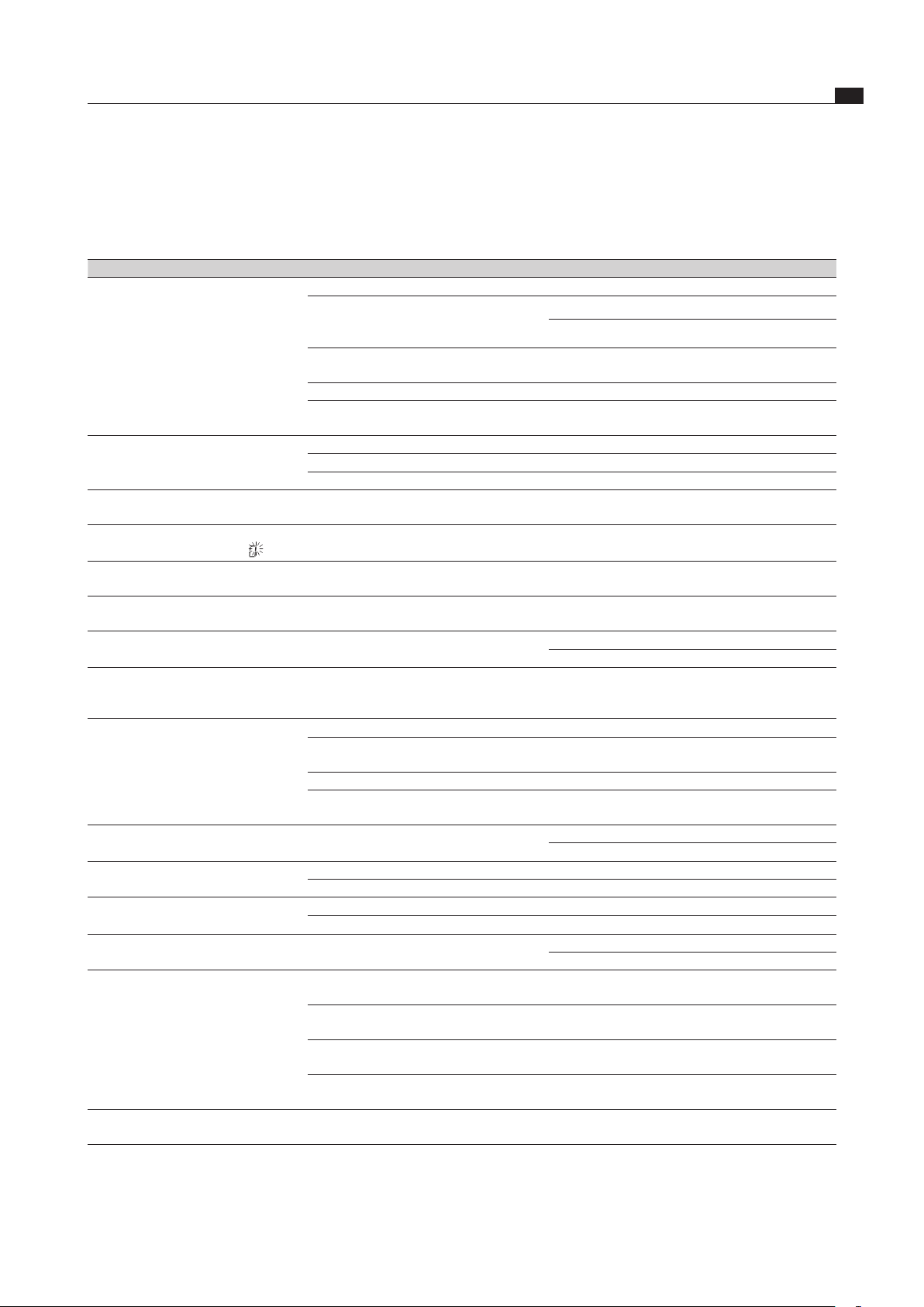
EN
41
Troubleshooting
www.bora.com
Observe all safety and warning information (see the Safety section).
Operating situation Cause Remedy
Cooktop extractor
will not switch on
Knob ring missing Place knob ring on the control knob
The fuse or automatic circuit breaker of the
electrical wiring system in the apartment
and/or house is defective.
Replace the fuse.
Switch the automatic circuit breaker back on
The fuse or the automatic circuit breaker
trips multiple times.
Contact BORA Service Team
The power supply is disconnected.
Have a specialist electrician inspect the power supply
The microfuse in the cooling device plug
connector for the control unit is defective.
Replace the fuse (type: T 3,15A/250V)
Fan motor does not start Cover flap not fitted or not fitted correctly Fit cover flap correctly
Grease filter not fitted or not fitted correctly Fit grease filter correctly
Fan motor faulty Contact BORA Service Team
Odours form when operating
the new cooktop extractor
Normal for brand new devices Odours stop forming after a few operating hours
The central control knob display shows
a segment turning clockwise
Knob ring not in the 0 position after fitting Turn the control knob to the 12 o’clock position
(= 0 position)
Control knob display
L
The childproofing feature is activated Switch off the childproofing feature
(see the Operation section).
Control knob display
/
Continuous operation (30 s) of the
control knob or control knob dirty
Release or clean the control knob
Control knob display
E
Home-in contact is interrupted Check cable or bridge for home-in contact
For example, window opened in exhaust mode.
Control knob display
F
Activated charcoal filter service life expired
Replace the activated charcoal filter, clean the
stainless steel grease filter if necessary, reset the
filter timer (see Cleaning or Operation section)
Control knob display
end
Foreign body blocking cover flap Remove the foreign body
Cover flap not properly slotted into the
guide
Press the cover flap gently from above on the
narrow side until you hear it slot into place
End switch faulty or out of place Contact BORA Service Team
Power failure when the cover flap is
opened or closed
Turn the control knob to position “0” and tap to
confirm. The cover flap will close.
Control knob display
E003
Electrical connection between touc
h surface
and knob ring (min. 3-5 s
econds).
Remove and clean the knob ring.
Wipe off any residual water on the touch surface
Control knob display
E0 1 1
Grease filter not fitted or not fitted correctly Fit grease filter correctly
Filter sensor faulty Contact BORA Service Team
Control knob display
E0 12
and
E0 13
Cover flap not fitted or not fitted correctly
Fit cover flap correctly
Cover flap sensor faulty Contact BORA Service Team
Control knob display
E0 19
Error evaluating the touch surface Twist control knob to “0” position
Contact BORA Service Team
The extraction performance of the
cooktop extractor has decreased.
The stainless steel grease filter is
heavily soiled
Clean or replace the stainless steel grease filter
The activated charcoal filter is heavily
soiled (recirculation only)
Replacing the activated charcoal filter
There is a foreign body in the air guiding
housing (e.g. cleaning cloth).
Remove the foreign body
The fan is defective or a duct connection
has become loose
Contact BORA Service Team
Cover flap not fully
open/closed
The movement process was interrupted by
an interruption in the electricity supply
Manual operation of the cover flap up to the end-
position (p. Chap. Assembly Table 6.13)
Tab. 9.1 Resolving a fault
After troubleshooting, turn the knob ring to the 12 o’clock position (0 position).
In all other cases, contact the BORA Service Team (see section ‘Warranty, technical service and spare parts) and
enter the error number displayed and the device type.
9 Troubleshooting
EN
42
Decommissioning, disassembly and disposal
www.bora.com
10 Decommissioning,
disassembly and
disposal
Observe all safety and warning information
(see the Safety section).
Follow the enclosed manufacturer’s information.
10.1 Decommissioning
Decommissioning is understood as final shutdown and
disassembly. Following decommissioning, the device can
either be installed into other units, sold on privately or
disposed of.
INFO Electricity and gas connections may only be
disconnected by qualified specialists.
To decommission, switch the device off
(see Operation section)
Disconnect the device from the power supply.
10.2 Disassembly
For removal, the device must be accessible for
disassembly and disconnected from the power supply.
Undo the mounting brackets.
Remove the silicone joints.
Disconnect the device from the extractor duct.
Remove the device from the worktop by lifting it
upwards.
Remove any other accessories.
Dispose of the old device and any contaminated
accessories as described under “ Environmentally-
friendly disposal”.
10.3 Environmentally-friendly disposal
Disposal of transport packaging
INFO The packaging protects the device from damage
in transport. The packaging materials have
been selected from environmental and disposal
perspectives and are therefore recyclable.
Returning the packaging to the materials cycle saves
resources and reduces waste volumes. Your specialist
supplier will take the packaging back.
Give the packaging to your specialist supplier
or
Dispose of the packaging properly in line with local
regulations.
Disposal of old appliance
Electrical devices marked with this label
may not be disposed of in domestic
waste at the end of their service
life. They must be disposed of at a
collection point for the recycling of old
electrical or electronic devices. You
can find information from your city or
district council.
Many electrical and electronic devices still contain
valuable materials. But they also contain damaging
materials which were necessary for them to function
properly and safely. These can damage human health or
the environment if disposed of improperly or incorrectly
handled.
Never put your old appliance in domestic waste.
Take the old appliance to a regional collection point
for return and recycling electrical and electronic
components and other materials.

EN
43
Warranty, technical service, spare parts, accessories
www.bora.com
11 Warranty, technical
service, spare parts,
accessories
Observe all safety and warning information (see the
Safety chapter).
11.1 BORA manufacturer’s warranty
BORA provides its end customers with a 2-year
manufacturer’s warranty for its products. The end
customer is entitled to this warranty in addition to the
statutory claims for defects against the sellers of our
products.
The manufacturer’s warranty applies to all BORA products
sold by authorised BORA dealers with the European
Union, with the exception of products labelled by BORA
as Universal products or accessories.
The manufacturer’s warranty starts as soon as the
BORA product is handed over to the end customer by
an authorised BORA dealer and is valid for 2 years.
By registering on www.bora.com/registration the
end customer has the possibility of extending the
manufacturer’s warranty.
The manufacturer’s warranty requires expert (in
accordance with the valid BORA ventilation handbook
and operating instructions at the time of installation)
installation of the BORA products by an authorised BORA
dealer. During use, the end customer is to adhere to the
specifications and instructions in the operating manual.
In order to file a warranty claim, the end customer is to
notify their dealer or BORA of the fault and must present
the receipt. Alternatively, the end customer can provide
proof of purchase by registering on www.bora.com.
BORA guarantees that all BORA products are free from
material and product defects. The defect must exist prior
to delivery of the product to the end customer. In the
event that a warranty claim is filed, the warranty shall not
commence anew.
BORA will correct defects in BORA products at its own
discretion by repairing or replacing the product. All costs
for the correction of defects under the manufacturer’s
warranty shall be assumed by BORA.
Expressly not covered by the BORA manufacturer’s
warranty are:
BORA products that were not sold by authorised BORA
dealers
Damage caused by non-adherence to the operating
instructions (including product care and cleaning) This
represents improper use.
Damage caused by normal use, e.g. traces of usage on
the cooktop
Damage caused by external influences (such as
transport damage, ingress of condensation, damage
caused by the elements such as a lightning strike)
Damage caused by repairs or attempts to repair not
made by BORA or persons authorised by BORA
Damage to the glass ceramic
Voltage fluctuations
Secondary damage or claims for damages beyond the
defect
Damage to plastic parts
Legal claims, particularly statutory claims for defects
or
product liability are not limited by the warranty.
If a defect is not covered by the manufacturer’s warranty,
the
end customer can employ the services of the BORA
technical service, however, they must cover the costs
themselves.
The laws of the Federal Republic of Germany apply to
these warranty conditions.
You can contact us by:
Telephone: +49 800 7890 0987 Monday to Thursday
from 08:00-18:00 and Friday from 08:00-17:00
Email: [email protected]
11.1.1 Warranty extension
You can extend the guarantee by registering at www.bora.
com/registration.
11.2 Service
BORA Service:
see reverse side of operating and assembly instructions
+800 7890 0987
In the case of faults you cannot fix yourself, contact
your BORA specialist supplier or the BORA Service
Team.
The BORA Service Team will require the type designation
and serial number of your device (FD number).
Both values are indicated on the rate plate in the warranty
insert and the underside of the device.
11.3 Spare parts
Only use original spare parts for repairs.
Repairs may only be carried out by the BORA Service
Team.
INFO Spare parts can be obtained from your BORA
dealer, the BORA online service website at www.
bora.com/service or by calling the service
number provided.

EN
44
Warranty, technical service, spare parts, accessories
www.bora.com
11.4 Accessories
BORA Pro Stainless steel grease filter PKA1FF
BORA Pro Cover flap PKA1VK
BORA Pro Cover flap All Black PKA1VKAB
BORA Pro Filter tray PKA1FW
BORA Power supply cable Type I UNLI (AUS)
BORA Power supply cable Type J UNLJ (CH)
BORA Power supply cable Type G UNLG (GB-IE)
BORA Pro knob ring PB1KR
BORA Pro knob ring All Black PB1KRAB
BORA window contact switch UFKS
Special accessory for recirculation systems:
BORA air purification box flexible ULBF
BORA activated charcoal filter set ULBAS for ULB3

EN
45
Notes:
www.bora.com
12 Notes:

EN
46
Notes:
www.bora.com


Germany:
BORA Lüftungstechnik GmbH
Rosenheimer Str. 33
83064 Raubling
Germany
T +49 (0) 8035 / 9840-0
F +49 (0) 8035 / 9840-300
www.bora.com
Austria:
BORA Vertriebs GmbH & Co KG
Innstraße 1
6342 Niederndorf
Austria
T +43 (0) 5373 / 62250-0
F +43 (0) 5373 / 62250-90
www.bora.com
Europe:
BORA Holding GmbH
Innstraße 1
6342 Niederndorf
Austria
T +43 (0) 5373 / 62250-0
F +43 (0) 5373 / 62250-90
www.bora.com
Australia - New Zealand:
BORA APAC Pty Ltd
100 Victoria Road
Drummoyne NSW 2047
Australia
T +61 2 9719 2350
F +61 2 8076 3514
www.bora-australia.com.au
+800 7890 0987