Loading ...
Loading ...
Loading ...
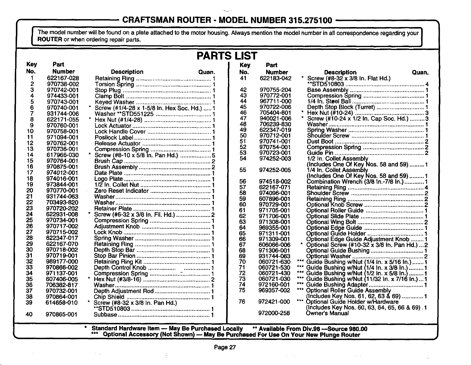
CRAFTSMAN ROUTER - MODEL NUMBER 315,275100
l The model number will be found on a plate attached to the motor housing. Always mention the model number in all correspondence regarding your I
....ROUTER or when ordering repair pads.
]
Key Part
No. Number
1 622167-028
2 970738-002
3 970742-001
4 974433-001
5 970743-001
6 970740-001
7 931744-006
8 622171-055
9 970760-001
10 970758-001
11 971094-001
12 970762-001
13 970736-001
14 617966-030
15 970764-001
16 970875-001
17 974012-001
18 974016-001
19 973844-001
20 970770-001
21 931744-063
22 703493-820
23 970720-202
24 622931-008
25 970734-001
26 970717-002
27 970715-002
28 622347-017
29 622167-070
30 970718-002
31 970719-001
32 989177-000
33 970866-002
34 971137-001
35 607406-005
36 706382-817
37 970732-001
38 970864-001
39 614658-010
40 970865-001
PARTS LIST
Key
Description Quan.
Retaining Ring .............................................. 1
Torsion Spring .............................................. 1
Stop Plug ...................................................... 1
Clamp Bolt .................................................... 1
Keyed Washer .............................................. 1
* Screw (#1/4-28 x 1-5/8 In. Hex Soc. Hd.) ..... 1
Washer **STD551225 .................................. 1
* Hex Nut (#1/4-28) ......................................... 1
Lock Actuator ................................................ 1
Lock Handle Cover ....................................... 1
Posilock Label ............................................... 1
Release Actuator .......................................... 1
Compression Spring ..................................... 1
* Screw (#8-10 x 5/8 In. Pan Hd.) ................... 5
Brush _,,__ap..................................................... 2
Brush Assembly ............................................ 2
Data Plate ..................................................... 1
Logo Plate ..................................................... 1
112 In. Collet Nut ........................................... 1
Zero Reset Indicator ..................................... 1
Washer .......................................................... 1
Washer .......................................................... 1
Retainer Plate ............................................... 1
* Screw (#6-32 x 318 In. Fil. Hd.) ..................... 2
Compression Spring ..................................... 1
Adjustment Knob .......................................... 1
Lock Knob ..................................................... 1
Spring Washer .............................................. 1
Retaining Ring .............................................. 1
Depth Stop Bar ............................................. 1
Stop Bar Pinion ............................................. 1
Retaining Ring Kit ......................................... 1
Depth Control Knob ................................. 1
Compression Spring ................... :................. 1
* Hex N,.ut(#3/8-16) ......................................... 2
Washer .......................................................... 1
Depth Adjustment Rod.................................. 1
Chip Shield ................................................... 1
* Screw (#8-32 x 3/8 In. Pan Hd.)
**STD510803 ................................................ 1
Subbase ........................................................ 1
Part
No. Number
41 622183-042
42 970755-204
43 970772-001
44 967711-000
45 970722-006
46 705404-801
47 940021-006
48 706239-830
49 622347-019
50 970712-001
51 970741-001
52 970754-001
53 970723-001
54 974252-003
55 974252-005
56 974518-002
57 622167-071
58 974096-001
59 607896-001
60 970729-001
61 971705-001
62 971706-001
63 971308-001
64 969355-001
65 971311-001
66 971309-001
67 606066-006
68 971306-001
69 931744-063
70 060721-630
71 060721-530
72 060721-430
73 060721-030
74 972160-001
75 969357-002
76 972421-000
972000-258
Description Quan.
* Screw (#8-32 x 3/8 In. Flat Hd.)
**STD510803 ................................................ 4
Base Assembly ............................................. 1
Compression .__pring..................................... 1
1/4 In. Steel Ballll............................................ 1
Depth Stop Block (Turret) ............................. 1
* Hex Nut (#10-24) .......................................... 3
* Screw (#10-24 x 1/2 In. Cap Soc. Hd.) ......... 3
Washer .......................................................... 1
Spring Washer .............................................. 1
Shoulder Screw ............................................ 1
Dust Boot ...................................................... 2
Compression Spdng ..................................... 2
Guide Pin ...................................................... 2
1/2 In. Collet Assembl)!.
(Includes One Of Key Nos. 58 and 59) ......... 1
1/4 In. Collet Assembly
(Includes One Of Key Noso 58 and 59) ......... 1
Combination Wrench (3/8 In.-7/8 In.) ............ 1
Retaining Ring .............................................. 4
Shoulder Screw ............................................ 2
Retainin_Rning .............................................. 2
Optional..nob Screw .................................... 2
Optional Roller Guide ................................... 1
Optional Slide Plate ...................................... 1
Optionat Wing Bolt ........................................ 2
Optional Edge Guide .................................... 1
Optional Guide Holder .................................. 1
Optional Edge Guide Adjustment Knob ........ 1
* Optional Screw_#10-32 x 3/8 In. Pan Hd.) ...2
Optional Guide Bushing ................................ 1
Optional Washer ........................................... 2
*** Guide Bushing w/Nut (1/4 In. x 5/16 In.) ....... 1
*** Guide Bushing w/Nut (1/4 In. x 3/8 In.} ......... 1
*** Guide Bushing w/Nut (1/2 In. x 5/8 In.) ......... 1
*** Guide Bushing w/Nut (11/32 In. x 7/16 In.)... 1
*** Guide Bushing Adapter ................................. 1
*** Optional Roller Guide Assembly
(_IncludesKey Nos. 61, 62, 63 &69) ............. 1
*** Optional Guide Holder w/Hardware
(includes Key Nos. 60, 63, 64, 65, 66 & 69), 1
Owner's Manual
* Standard Hardware Item m May Be Purchased Locally ** Available From Div.98 ---Source 980.00
*** Optional Accessory (Not Shown) -- May Be Purchased For Use On Your New Plunge Router
Page 27
Loading ...