Loading ...
Loading ...
Loading ...
ADJUSTMENTS
DEPTH STOP SYSTEM (Continued)
5. Raise cutter by depressing plunge release actuator.
6. Place router on flat surface, and lower router until tip of
cutter barely touches flat surface.
7. Squeeze plunge lock actuator to lock cutter at "zero"
depth of cut.
8. Turn adjustment knob counterclockwise to lower stop
bar against the stop, then tighten lock knob securely.
The highest stop now becomes the "zero" depth of cut
setting.
9. Depress plunge release actuator and raise router. Ro-
tate stop block so that next highest depth stop aligns
with stop bar. This locates cutter for the initial pass.
10. Rotate depth stop blOck after each pass. Make as
many successive passes as needed to obtain desired
depth of cut, progressively lowering router to next depth
of cut setting with each pass.
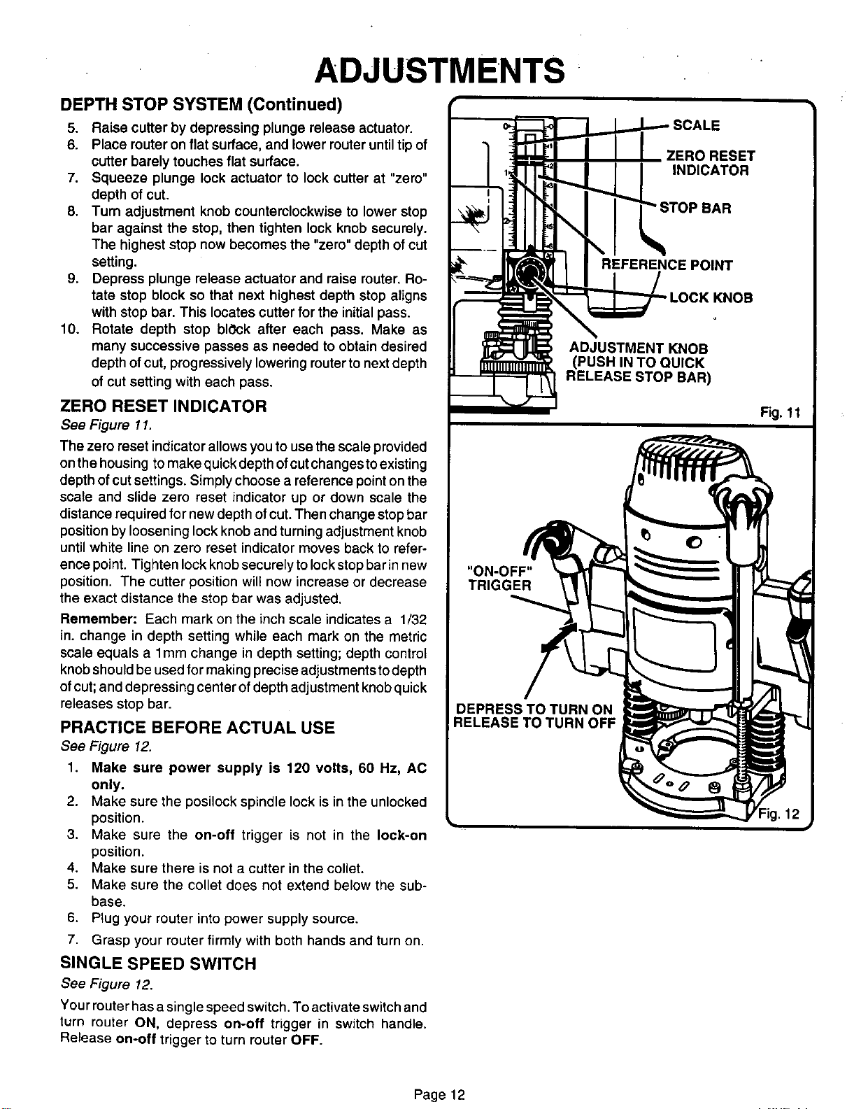
ZERO RESET INDICATOR
See Figure 11.
The zero reset indicator allowsyou to usethe scale provided
on the housing tomake quick depthofcutchanges toexisting
depth of cut settings. Simply choose a reference point on the
scale and slide zero reset indicator up or down scale the
distance required for new depth ofcut. Then change stopbar
positionby loosening lock knoband turningadjustment knob
until white line on zero reset indicator moves back to refer-
ence point. Tighten lock knobsecurely to lockstopbar in new
position. The cutter position will now increase or decrease
the exact distance the stop bar was adjusted.
Remember: Each mark on the inch scale indicates a 1/32
in. change in depth setting while each mark on the metric
scale equals a lmm change in depth setting; depth control
knobshouldbe used for making precise adjustments todepth
ofcut;and depressing center of depth adjustment knobquick
releases stop bar.
PRACTICE BEFORE ACTUAL USE
See Figure 12.
1. Make sure power supply is 120 volts, 60 Hz, AC
only.
2. Make sure the posilock spindle lock is in the unlocked
position.
3. Make sure the on-off trigger is not in the lock-on
position.
4. Make sure there is not a cutter in the collet.
5. Make sure the collet does not extend below the sub-
base.
6. Plug your router into power supply source.
7. Grasp your router firmly with both hands and turn on.
SINGLE SPEED SWITCH
See Figure 12.
Your router has a single speed switch. To activate switch and
turn router ON, depress on-off trigger in switch handle.
Release on-off trigger to turn router OFF.
"ON-OFF"
TRIGGER
DEPRESS TO TURN ON
RELEASE TO TURN OFF
REFERENCE POINT
Page 12
Loading ...
Loading ...
Loading ...