Loading ...
Loading ...
Loading ...
OPERATION
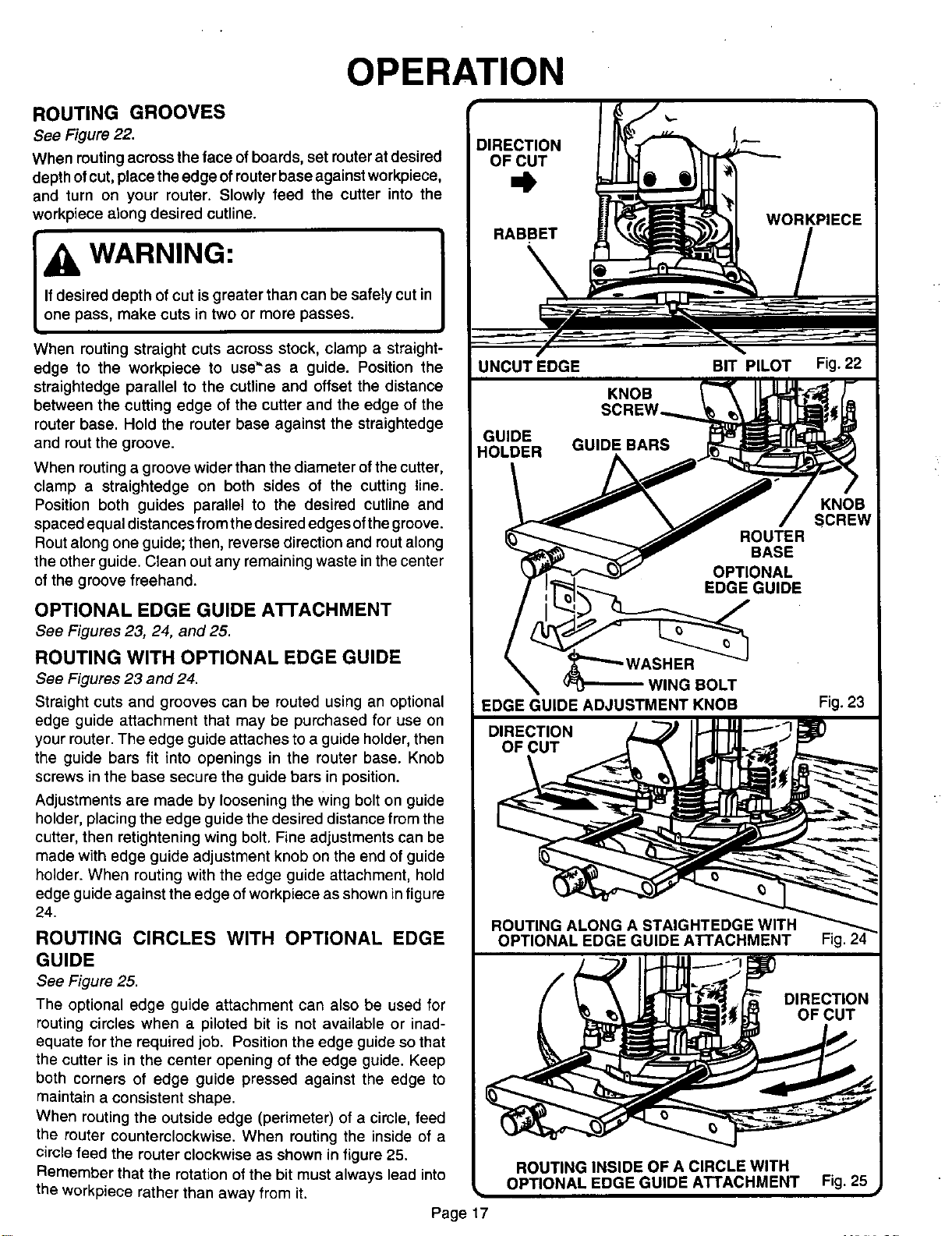
ROUTING GROOVES
See Figure 22.
When muting across the face ofboards, set muter at desired
depth ofcut, place the edge of routerbase againstworkpiece,
and turn on your router. Slowly feed the cutter into the
workpiece along desired cutline.
WARNING:
When routing straight cuts across stock, clamp a straight-
edge to the workpiece to use_'as a guide. Position the
straightedge parallel to the cutline and offset the distance
between the cutting edge of the cutter and the edge of the
router base. Hold the router base against the straightedge
and rout the groove.
When routing a groove wider than the diameter of the cutter,
clamp a straightedge on both sides of the cutting line.
Position both guides parallel to the desired cutline and
spaced equal distances from the desired edges ofthe groove.
Rout along one guide; then, reverse direction and rout along
the other guide. Clean out any remaining waste in the center
of the groove freehand.
OPTIONAL EDGE GUIDE A'n'ACHMENT
See Figures 23, 24, and 25.
ROUTING WITH OPTIONAL EDGE GUIDE
See Figures 23 and 24.
Straight cuts and grooves can be routed using an optional
edge guide attachment that may be purchased for use on
your router. The edge guide attaches to a guide holder, then
the guide bars fit into openings in the router base. Knob
screws in the base secure the guide bars in position.
Adjustments are made by loosening the wing bolt on guide
holder, placing the edge guide the desired distance from the
cutter, then retightening wing bolt. Fine adjustments can be
made with edge guide adjustment knob on the end of guide
holder. When routing with the edge guide attachment, hold
edge guide against the edge of workpiece as shown in figure
24.
ROUTING CIRCLES WITH OPTIONAL EDGE
GUIDE
See Figure 25.
The optional edge guide attachment can also be used for
routing circles when a piloted bit is not available or inad-
equate for the required job. Position the edge guide so that
the cutter is in the center opening of the edge guide. Keep
both corners of edge guide pressed against the edge to
maintain a consistent shape.
When routing the outside edge (perimeter) of a circle, feed
the router counterclockwise. When routing the inside of a
circle feed the router clockwise as shown in figure 25.
Remember that the rotation of the bit must always lead into
the workpiece rather than away from it.
Page 17
ROUTER
BASE
OPTIONAL
EDGE GUIDE
WING BOLT
EDGE GUIDE ADJUSTMENT KNOB
ROUTING ALONG A STAIGHTEDGE WITH
OPTIONAL EDGE GUIDE ATTACHMENT
KNOB
SCREW
Fig. 23
Loading ...
Loading ...
Loading ...