Loading ...
Loading ...
Loading ...
20306741
14
BLDV7 Series Gas Fireplace
VENTING INSTALLATION INFORMATION
TWIST LOCK PIPES
When using twist lock pipe it is not necessary to use
sealant on the joints.
To join twist lock pipes together, simply align the beads of
the male end with the grooves of the female end, twisting
thepipeuntiltheangeonthefemaleendcontactsexter-
nalangeonthemaleend.Itisrecommendedthatyou
secure the joints with three (3) sheet metal screws, how-
ever, this is not mandatory with twist lock pipe. Figure 9
NOTE: Sealant is not required to assemble replace
venting. Do not use silicone sealant at the inner ue
exhaust connections.
To make it easier to assembly the joints, we suggest put-
ting a lubricant (Vaseline or similar) on the male end of the
twist lock pipe prior to assembly.
TWL100
Twist Lock Pipe
3/12/99 djt
Male End
Female End
Screw Holes
TWL100
Figure 9 -
Twist-lock Pipe Joints
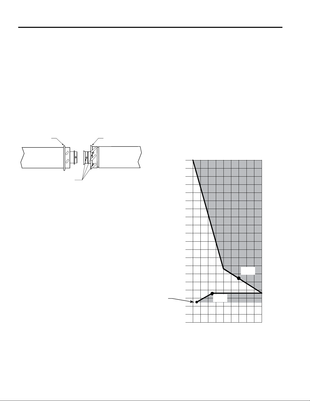
HOW TO USE THE VENT GRAPH
The Vent Graph should be read in conjunction with the
following vent installation instructions to determine the re-
lationshipbetweentheverticalandhorizontaldimensions
of the vent system.
1.Determine the height of the center of the horizontal
vent pipe exiting through the outer wall. Using this di-
mension on the Sidewall Vent Graph, Figure 10, locate
the point intersecting with the slanted graph line.
2. From the point of this intersection, draw a vertical line
to the bottom of the graph.
3.Select theindicateddimension,andposition there-
place in accordance with same.
EXAMPLE A:
Iftheverticaldimensionfromtheooroftheunitis11’(3.4
m)thehorizontalruntothefaceoftheouterwallmustnot
exceed 14’ (4.3 m).
EXAMPLE B:
Iftheverticaldimensionfromtheooroftheunitis7’(2.1
m),thehorizontalruntothefaceoftheouterwallmustnot
exceed 7’ (2.1 m).
Refer to Page 18 for requirements for snorkels.
FP2337
sidewall vent graph
2 4 6 8 10 12 14 16 18 20
40
38
36
34
32
30
28
26
24
22
20
18
16
14
12
10
8
6
4
2
Figure 10 -
Rear Wall Venting Graph
Horizontaldimensionfromthenishedoutsidewall
tothecenterofthepipeonthereplace
Vertical Dimension From the Floor of Unit to the
CenteroftheHorizontalVentPipe
57" from
oor to
center
eg: A
eg: B
Loading ...
Loading ...
Loading ...