Loading ...
Loading ...
Loading ...
(2)
permit each trunnion to "'stip ' when tapped with
a mallet or plastlc-tipped hammer. (If loosened
completely, it would be almost impossib_e to
achieve an accurate Qdiustment. )
Shift the two trunnions by topping them lightly
until the two measurements described in the pre-
ceding instructions are equal. Tighten the trun-
nion screws and recheck measurements to make
sure tightening screws did nat a_ter the setting.
Several trials may be required to produce an
accurate setting.
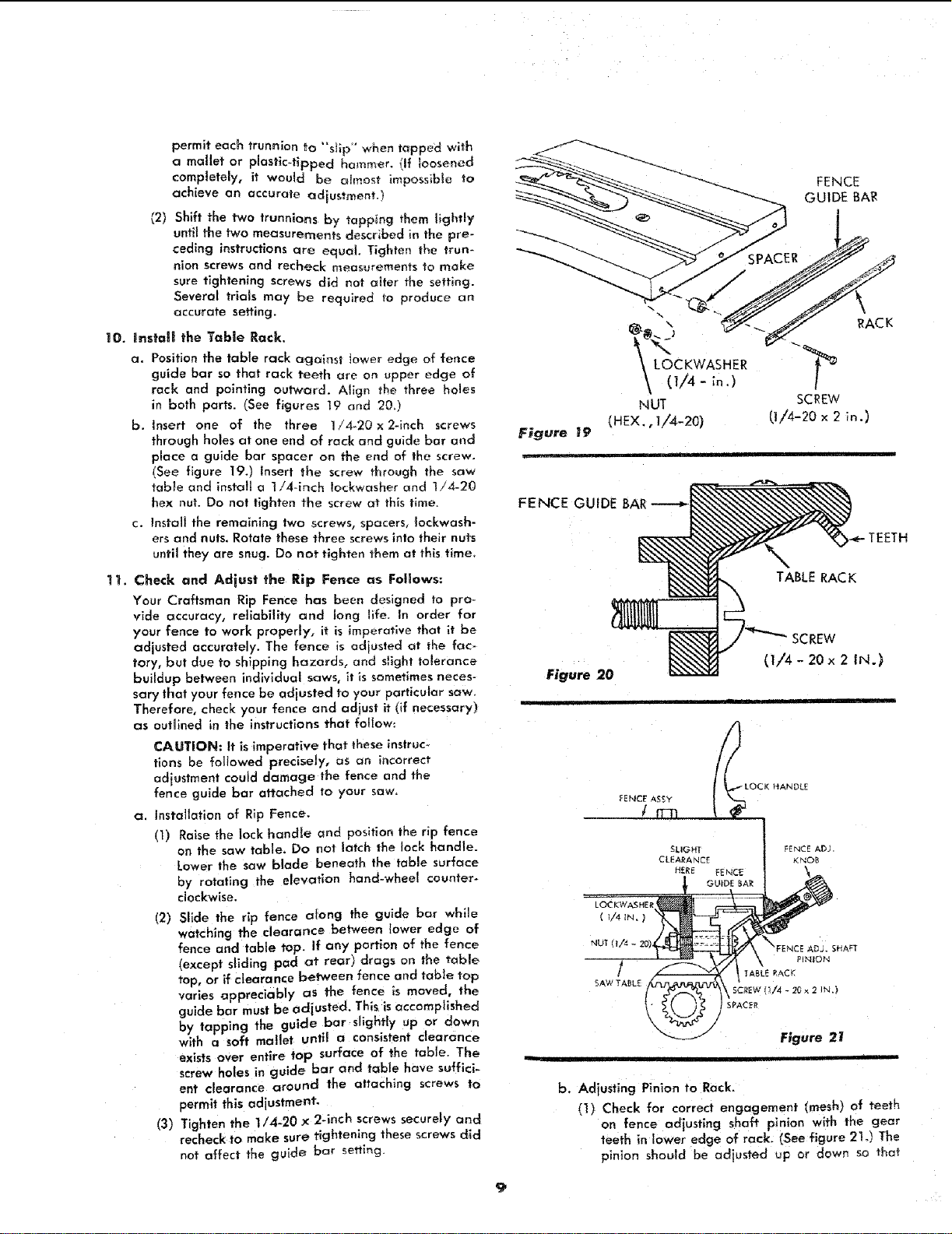
10. Ins_'ali the Table Rack,
a. Position the table rack against lower edge of fence
guide bar so that rack teeth are on upper edge of
rack and pointing outward. Align the three ho_es
in both parts. (See figures 19 and 20.)
b. Insert one of the three 1/4-20 x 2-inch screws
through holes at one end of rack and guide bar and
place a guide bar spacer on the end of the screw.
(See figure 19.) Insert the screw through the saw
table and install a 1!4-inch !ockwasher and 174-20
hex nut. Do not tighten the screw at this time.
c. Instalt the remaining two screws, spacers, Iockwash-
ers and nuts. Rotate these three screws into their nuts
until they are snug. Do not tighten them at this time,
11. Check and Adiust the Rip Fence as Follows:
Your Craftsman Rip Fence has been designed to pro-
vide accuracy, reliability and long llfe. In order for
your fence to work properly, it is imperative that it be
adjusted accurately. The fence is adjusted at the fac-
tory, but due to shipping hazards, and s_ight tolerance
buildup between individual saws, it is sometimes neces-
sary that your fence be adjusted to your particular saw.
Therefore, check your fence and adjust it (if necessary)
as outlined in the instructions that follow:
CAUTION: It is imperative that these instruc_
;'ions be followed precisely, as an incorrect
adiustment could damage the fence and the
fence guide bar attached to your saw.
a. Installation of Rip Fence.
(1) Raise the lock handle and position the rip fence
on the saw table, Do not latch the lock handle.
Lower the saw blade beneath the table surface
by rotating the elevation hand-wheel counter°
clockwise.
12) Slide the rip fence atong the guide bar while
watching the clearance between lower edge of
fence and table top. if any portion of the fence
(except sliding pad at rear) drags on the table
top, or if clearance between fence and table top
vades appreciably as the fence is moved, the
guide bar must be adius ted. This is accomplished
by tapping the guide bar slightly up or down
with a soft mallet until a consistent clearance
exists over entire top surface of the table. The
screw holes in guide bar and table have suffici-
ent clearance around the attaching screws to
permit this adjustment-
(3) Tighten the 1/4-20 × 2qnch screws securely and
recheck to make sure tightening these screws did
not affect the guide bar setting.
FENCE
GUIDE BA!R
@ \
_ LC)CKWASHER
\ fl!4
NUT
(HEX., I/4-20)
RACK
SCREW
(I/4-20 × 2 _o.)
FENCE GUIDE
TEETH
TABLE RAC K
;REW
(1/4- 20 x 2 iN.)
Figure 20
i i
LOCKWASHER
( I/4 IN. _
b. Adjusting Pinion to Rack.
(1) Check for correct engagement (mesh) of teeth
on fence adjusting shaft pinion with the gear
teeth in lower edge of rack. (See figure 21.) The
pinion should be adiusted up or down so that
Loading ...
Loading ...
Loading ...