Loading ...
Loading ...
Loading ...
(7) Rotate the tilt hand-wheel counterclockwise ap-
proximately three turns, then rotate it clockwise
until it stops. Check the saw again with the
square as shown in figure 6. If the adjustment
is correct (blade square with table surface),
tighten the set screw in the stop collar securely.
NOTE: Several trial adjustments may be re-
quired in order to produce an accurate
adjustment of the stop collar. If the first trial
fails to produce an accurate setting, it issug-
gested that the operator determine which
direction the stop collar needs to be rotated
for a correction and turn the collar in small
increments (checking each time) until the
adjustment is correct. Be sure to tighten one
of the collar set screws after each adjustment
to prevent the collar from slipping on the
tilt screw when it comes into contact with the
saw cradle.
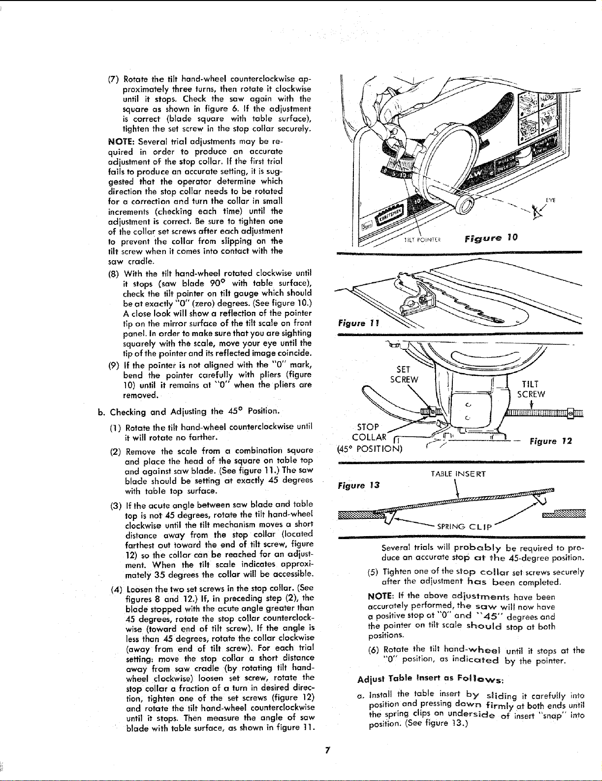
(8) With the tilt hand-wheel rotated clockwise until
it stops (saw blade 90 ° with table surface),
check the tilt pointer on tilt gauge which should
be at exactly "0" (zero) degrees. (See figure 10.)
A close look will showa reflection of the pointer
tip on the mirror surface of the tilt scale on front
panel. In order to make surethat you are sighting
squarely with the scale, move your eye until the
tip of the pointer and its reflected image coincide.
(9) If the pointer is not aligned with the "0" mark,
bend the pointer carefully with pliers (figure
10) until it remains at "'0" when the pliers are
removed.
b. Checking and Adjusting the 45° Position.
fl ) Rotate the tilt hand-wheel counterclockwise until
it will rotate no farther.
(2) Remove the scale from a combination square
and place the head of the square on table top
and against saw blade. (See figure 1I.) The saw
blade should be setting at exactly 45 degrees
with table top surface.
(3) Efthe acute angle between saw blade and table
top is not 45 degrees, rotate the tilt hand-wheel
clockwise until the tilt mechanism moves a short
distance away from the stop collar (located
farthest out toward the end of tilt screw, figure
12) so the collar can be reached for an adjust-
ment. When the tilt scale indicates approxi-
mately 35 degrees the collar will be accessible.
(4) Loosen the two setscrews in the stop collar. (See
figures 8 and 12.) If, in preceding step (2), the
blade stopped with the acute angle greater than
45 degrees, rotate the stop collar counterclock-
wise (toward end of tilt screw). If the angle is
less than 45 degrees, rotate the collar clockwise
(away from end of tilt screw). For each trial
setting: move the stop collar a short distance
away from saw cradle (by rotating tilt hand-
wheel clockwise) loosen set screw, rotate the
stop collar a fraction of a turn in desired direc-
tion, tighten one of the set screws (figure 12)
and rotate the tilt hand-wheel counterclockwise
until it stops. Then measure the angle of saw
blade with table surface, as shown in figure 11.
\
I!_1 TILT
scREw
c. f
Figure 12
TABLE INSERT
Figure I3 _
Several trials will probc_bly be required to pro-
duce an accurate stop at the 45-degree position.
(5) Tighten one of the stop collar set screws securely
a{ter the adius_.ment has been completed.
NOTE: If the above adjustments have been
accurately performed, the saw will now have
a positive stop at "0" and "'45" degrees and
the pointer on tilt scale should stop at both
positions.
(6) Rotate the tilt hand-vcheel until it stops at the
"0'" position, as indicated by the pointer.
Adjust Table Insert as Follows:
a, Install the table inser,_ by" sliding it carefully into
position and pressing down firmly at both ends until
the spring clips on under'Side of insert "snap" into
position. (See figure 13.)
Loading ...
Loading ...
Loading ...