Loading ...
Loading ...
Loading ...
procedures
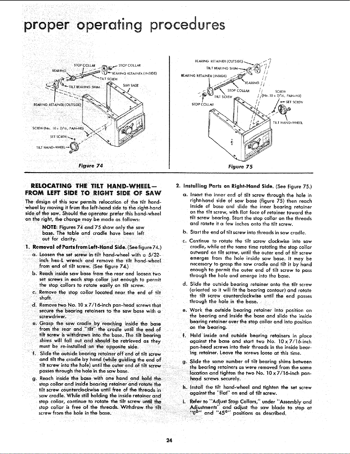
Figure 74
SAW BASE
NSIDE|
BEARING RETAINER
\
\
Figure 75
RELOCAT|NG THE TnLT HAND-WHEEL--
FROM LEFT SIDE TO RIGHT SIDE OF SAW
The design of this saw permits relocation of the tilt hand-
wheel by moving it from the left-hand side to the right-hand
side of the saw. Should the operator prefer this hand-wheel
on the right, the change maybe made as follows:
NOTE: Figures 74 and 75 show only the saw
base. The table and cradle have been left
out for darity.
1. Removal of Partsfrom Left-Ha nd Side. (See figure740
a. Loosen the set screw intilt hand-wheel with a 5/32-
inch hex-L wrench and remove the tilt hand-wheel
from end of tilt screw. (See figure 74.)
b. Reach inside saw base from the rear and loosen two
set screws in each stop collar just enough to permit
the stopcollars 1o rotate easily on tilt screw
c. Remove the stop collar located near the end of tilt
shaft.
d. Remove two No. 10 x 7/1 6-inch pan-head screwsthat
secure the bearing retainers to the saw base with a
screwdriver.
e. Grasp 1he saw cradle by reaching nsde the base
from the rear end flit" the cradle until the end of
tiff screw is withdrawn into the base. The tilt bearing f.
shims will fall out and should be retrieved as they
must be re-lnstalled on the opposite side.
f. Slide the outsidebearing retainer off end of tilt screw
and tilt the cradle by hand (while guiding the end of
tilt screw intothe hole) until the outer end of tilt screw g"
passesthrough the holein the saw base.
g. Reach inside the base with one hand and hold the
stop collar and inside bearing retainer and rotate the
2. instai_ing Parts on Right-Hand Side. (See figure 75.)
a. Insert the inner end of tilt screw through the hole in
right-hand side of saw base (figure 75) then reach
inside of base and slide the inner bearing retainer
on the tilt screw, with flat face of retainer toward the
tilt screw bearing. Start the stop collar on the threads
and rotate it a few inches onto the tilt screw.
b. Start the end of tilt screw into threads in saw cradle.
c. Continue to rotate the tiff screw clockwise into saw
cradle, while at the same time rotating the stop collar
outward on tilt screw, until the outer end of flit screw
emerges from the hole inside saw base. it may be
necessary to grasp the saw cradle and tilt it by hand
enough to permit the outer end of tilt screw to pass
through the hole and emerge into the base.
d. Slide the outside bearing retainer onto the tilt screw
(oriented soit wilt fit the bearing contour) and rotate
the tilt screw counterc!ockwise until the end passes
through the hole in the base.
e. Work the outside bearing retainer into position on
the bearing and inside the base and siide the inside
bearing retainer over the stop cellar and into position
on the bearing.
Hold inside and outside hearing retainers in place
against the base and start two No. 10 x 7/16-1nch
pan-head screws into their threads in the inside bear-
mg retainer. Leave the screws loose at this time.
Slide the same number of tilt bearing shims between
the bearing retainers as were removed from the same
location and tighten the two No. 10 x 7/16-inch pan-
head screws securely.
tilt screw counterclockw se unt I free of the threads in h. Install the t!!t, hand-wheel and tighten the set screw
agalnstthe riot on ena of tilt screw
saw cradle. White still holding the inside retainer and
stop collar, continue to rotate the tilt screw until the i. Refer to "'Adjust Step Collars," under "'Assemblyand
stop collar is free of the threads. Withdraw the tiff Adjustments' and adjust the saw b ade to stop at
screw from the hole in the base. 0 and 45 poslhons as described.
24
Loading ...
Loading ...
Loading ...