Loading ...
Loading ...
Loading ...
proper operating procedures
ORANG[
PUR_£
RIP CUTS DEPTH OF CUT
LOCK UflLOCK
MITER CUTS
tIGHT BLUE v'ELLOW
Figure 56
Figure 57
i,
WIDTH OF CUT-_
SOC KET-HEAD
rSCREWS
CUT INDICATOR
CUT-INDICATOR SHOES
Figure 58
P OPEROPEEATJNGPROCEDURES
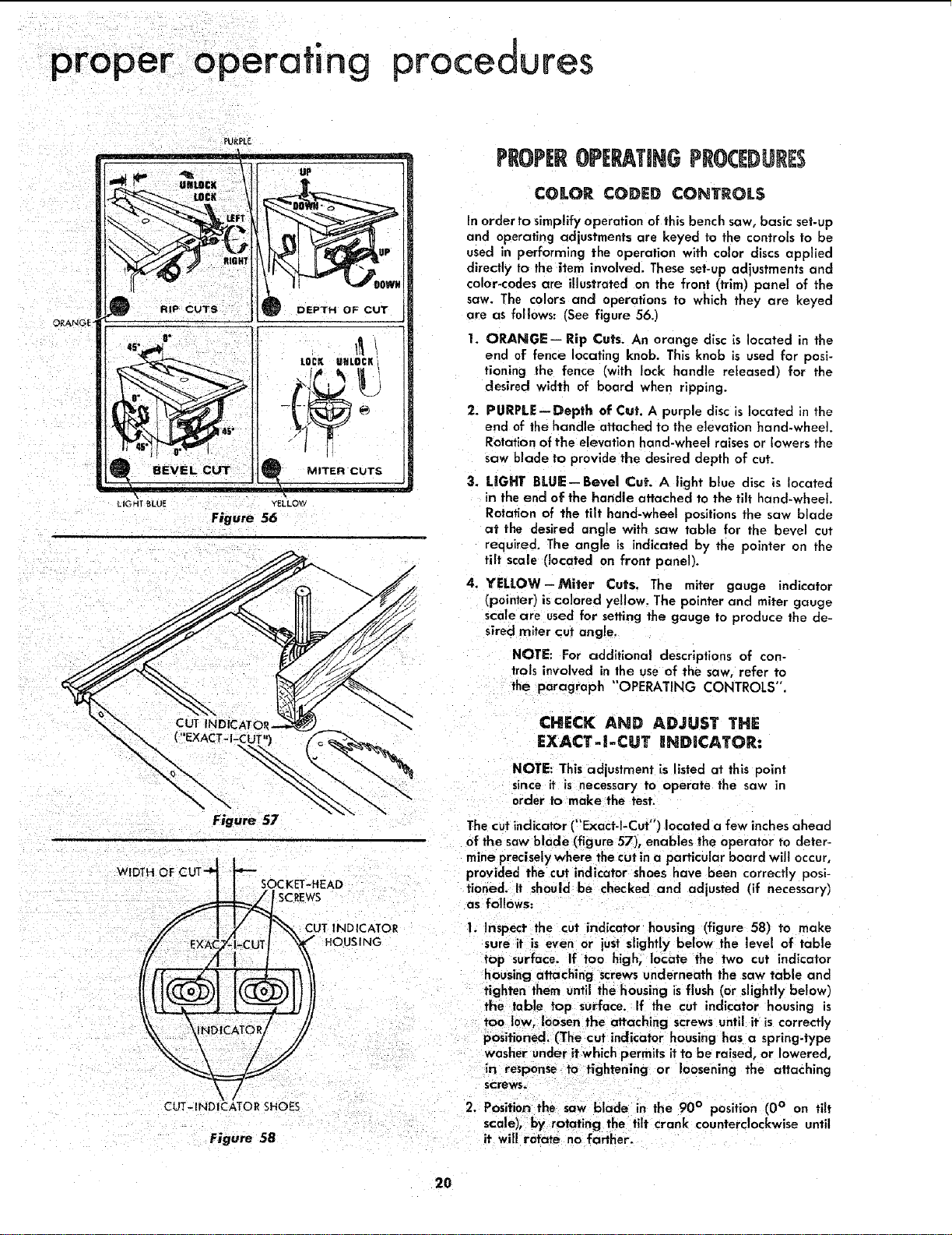
COLOR CODED CONTROLS
In order to simplify operation of this bench saw, basic set-up
and operating adjustments are keyed to the controls to be
used in performing the operation with color discs applied
directly to the item involved. These set-up adjustments and
color-codes are illustrated on the front (trim) panel of the
saw. The colors and operations to which they are keyed
are as follows: (See figure 56.)
1. ORANGE-- Rip Cuts. An orange disc is located in the
end of fence locating knob. This knob is used for posi-
tioning the fence (with lock handle released) for the
desired width of board when ripping.
2. PURPLE--Depth of Cut. A purple disc is located in the
end of the handle attached to the elevation hand-wheel.
Rotation of the elevation hand-wheel raises or lowers the
saw blade to provide the desired depth of cut.
3. LIGHT BLUE--Bevel Cut. A light blue disc is located
in the end of the handle attached to the tilt hand-wheel.
Rotation of the tilt hand-wheel positions the saw blade
at the desired angle with saw table for the bevel cut
required, The angle is indicated by the pointer on the
tilt scale (located on front panel).
4. YELLOW-Miter Cuts. The miter gauge indicator
(pointer) is colored yellow. The pointer and miter gauge
scale are used for setting the gauge to produce the de-
sired -niter cut angle.
NOTE: For additional descriptions of con-
trois involved in the use of the saw, refer to
the paragraph "OPERATING CONTROLS".
CHECK AND ADJUST THE
EXACT-I-CUT gNDICATOR:
NOTE: This adjustment is listed at this point
since it is necessary TO operate the saw in
order to make the test.
The cut indicator ("Exact-I-Cut') located a few inchesahead
of the saw blade (figure 57), enables the operator to deter-
mine preciselywhere the cut in a particular board will occur,
provided the cut indicator shoes have been correctly posi-
tioned, it should be checked and adjusted (if necessary)
as follows:
1. Inspect the cut indicator housing (figure 58) to make
sure it is even or just slightly below the level of table
top surface. If too high, locate the two cut indicator
housing attaching screwsunderneath the saw table and
fig hten them until the housing is flush (or slightly below)
the table top surface. If the cut indicator housing is
too 10w, loosen the attaching screws until it is correctly
positioned. (The cut indicator housing has a spring.type
washer under it which permits it to be raised, or lowered,
in response to ffghtening or loosening the attaching
screws.
2. Position the saw blade in the 90 ° position (0 ° on tilt
scale), by rotating the tilt crank counterclockwise until
it will rotate no farther.
2O
Loading ...
Loading ...
Loading ...