Loading ...
Loading ...
Loading ...
adiustments
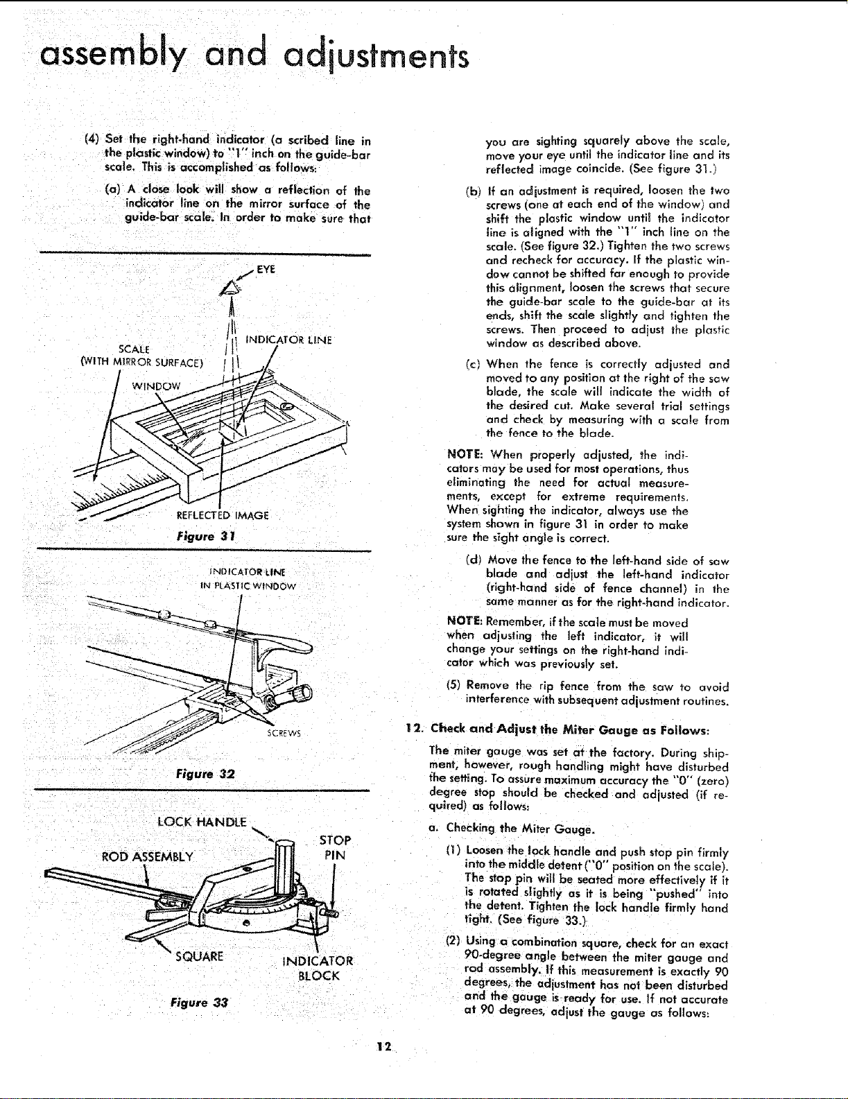
(4) Set the right-hand indicator (a scribed line in
the plastic window) to "'1" inch on the guide-bur
scale, This is accomplished as follows:
(a) A close look will show a reflection of the
indicator line on the mirror surface of the
guide-bar scale. In order to make sure that
SCALE
(WITH MIRROR SURFACE)
WINDOW
REFLECTEDIMAGE
Figure 31
IND ICATOR LINE
IN PLASTIC WINDOw
!
$CREWS
Figure 32
LOCK HANDLE
ROD ASSEMBLY
STOP
PIN
SQUARE
INDICATOR
BLOCK
Figure 33
yeu are sighting squarely above the scale,
move your eye until the indicator line and its
reflected image coincide. (See figure 31.1
(b) If an adiustrnent is required, loosen the two
screws cone at each end of the window] and
shift the plastic window untit the indicator
line is aligned with the "'!" inch line on the
scale, fSee figure 32.) Tighten the two screws
and recheck for accuracy. If the plastic win-
dow cannot be shifted far enough to provide
this alignment, loosen the screws that secure
the guide-bar scale to the gulde-bar at its
ends, shift the scale slightly and tighten the
screws. Then proceed to adjust the plastic
window as described above.
(c)
When the fence is correctly adjusted and
moved to any position at the right of the saw
blade, the scale will indicate the width of
the desired cut. Make several trial settings
and check by measuring with a scale from
the fence to the blade.
NOTE: When properly adjusted, the indi-
cators may be used for most operations, thus
eliminating the need for actual measure-
ments, except for extreme requirements.
When sighting the indicator, always use the
system shown in figure 31 in order to make
sure the sight angle is correct.
(d) Move the fence to the left-hand side of saw
blade and adjust the left-hand indicator
(right-hand side of fence channel) in the
same manner as for the right-hand indicator.
NOTE: Remember, if the scale must be moved
when adjusting the left indicator, it will
change your settings on the right-hand indi-
cator which was previously set.
(5) Remove the rip fence from the saw to avoid
interference with subsequent adjustment routines.
12. Check and Adjust the Miter Gauge as Follows:
The miter gauge was set at the factory. During ship-
ment, however, rough handling might have disturbed
the setting, To assure maximum accuracy the "0" (zero)
degree stop should be checked and adjusted (if re-
quired) as follows:
a, Checking the Miter Gauge.
(1) Loosen the lock handle and push stop pin firmly
into the middle detent ("0"" position on the scale).
The stop pin will be seated more effectively if it
is rotated slightly as it is being "pushed" into
the detent. Tighten the lock handle firmly hand
tight, (See figure 33,)
(2) Using a combination square, check for an exact
90-degree angle between the miter gauge and
rod assembly. If this measurement is exactly 90
degrees, the adjustment has not been disturbed
and the gauge is-ready for use. If not accurate
at 90 degrees, adjust the gauge as follows:
12
Loading ...
Loading ...
Loading ...