Loading ...
Loading ...
Loading ...
EN
20
Installation
www.bora.com
Push the substructure module [2] into the silence
module [3].
INFO Never place strain on the cooktop extractor
frame when installing the substructure module.
This will deform the cooktop extractor frame.
Connect the substructure module [2] to the cooktop
extractor frame [1] by carefully pressing the
substructure module [2] upwards into the relevant
cooktop extractor frame brackets [1]. The module
should audibly click into place on each of the long
sides of the extractor frame to indicate that it has been
correctly connected.
click
click
click
click
Fig. 6.23 Attaching the substructure module
Use the sealing tape (UDB) provided to adhere the
substructure module [2] to the silence module [3].
Place the control unit [8] in the plinth area.
INFO Position the plinth fan and the control unit in
such a way that they are easily accessible and
removable for maintenance work.
The maximum exhaust air duct length is 6 m.
The minimum cross-section of the air ducts must be
176 cm². This corresponds to a round pipe with a
diameter of 150 mm.
For the ducting, only use stable duct elements with
smooth pipe interiors. Do not use flexible or fabric
tubes.
The exhaust air must be directed outside or to the
recirculation unit through appropriate ducts.
For further planning examples and notices, please see
the ventilation handbook (not included in the scope of
delivery).
INFO When attaching the sealing tape, ensure that
an airtight seal with the connection duct piece
is created when the tape is compressed.
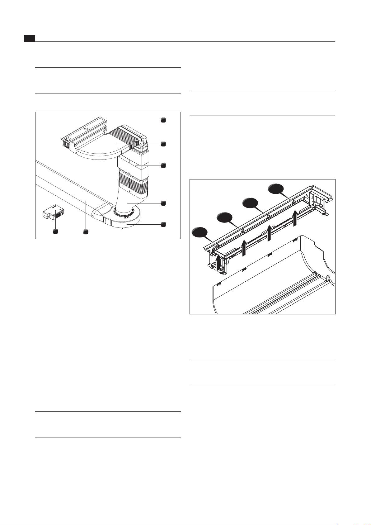
6.5.3 Installation – standard set-up
1
2
3
4
5
6
8
Fig. 6.22 Standard set-up
[1] Cooktop extractor
[2] Substructure module
[3] Silence module
[4] Transition piece (curved or straight)
[5] Universal plinth fan
[6] Air duct or recirculation unit
[7] Protective grid (not visible)
[8] Control unit
Position the plinth fan [5].
To facilitate positioning, the inlet nozzle on the plinth
fan can be removed. To do this, please see the
assembly instructions for the ULS universal plinth fan.
Push the transition piece [4] onto the inlet nozzle of
the plinth fan [5].
You can also use the sealing tape provided (UDB) to
adhere the connections together.
Push the silence module [3] onto the transition piece
[4].
Tape the transition piece [4] to the silence module [3].
INFO To secure the silence module, this must to
screwed to the transition piece to relieve the
strain on the substructure module.
Now screw together the silence module [3] and the
transition piece [4].
Insert the protective grid [7] into the upper opening on
the silence module [3].
Loading ...
Loading ...
Loading ...