Loading ...
Loading ...
Loading ...
EN
15
Installation
www.bora.com
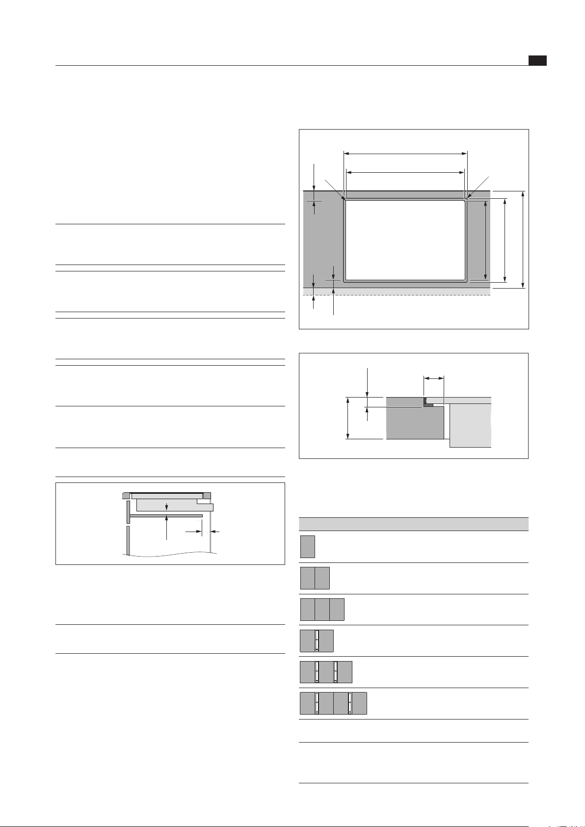
Flush installation
x
≥ 50
A ±2
B ±2
519 ±2
≤ R5
≤ R5
≥ 50
495 ±2
≥ 600
Fig. 6.3 Flush installation
5 +0,5
12
10 – 40
Fig. 6.4 Groove dimensions cut-out
Cut-out dimensions when installing cooktops only or cook-
tops and the BORA cooktop extractor alongside each other:
Cooktops/cooktop extractor A in mm B in mm
1/0 344 320
2/0 685 661
3/0 1026 1002
2/1 776 752
3/2 1208 1184
4/2 1549 1525
Tab. 6.2 Cut-out dimensions
INFO If the induction glass ceramic wok is used, the
groove dimensions must be increased to 7 mm
for flush installation.
A return flow aperture > 500 cm
2
is required in the
kitchen units for recirculation appliances (e.g. by
shortening the plinth boards or using suitable slatted
plinths).
6.3.3 Cooktop air intake
The components in the cooktop which generate heat are
automatically cooled. The warm air is extracted by fans
(cold air flow).
INFO In order to retain the full functionality of
the cooktop in the long term, there must be
sufficient ventilation underneath the cooktop.
INFO The performance of the cooktop is impaired or
the cooktop overheats if the warm air below
the cooktop cannot escape.
INFO If the cooktop overheats, performance
is reduced or the cooktop switches off
completely (see Overheating protection).
INFO For sufficient air intake, an opening cross-
section in the kitchen units of at least 50 cm
2
is recommended.
Ensure there is sufficient ventilation underneath the
cooktop.
INFO The cable protection (false floor) must not
prevent sufficient ventilation.
> 20
50
Fig. 6.2 Side view of the cable protection and ventilation
6.4 Cut-out dimensions
INFO All dimensions from the front edge of the
front cover.
Please note the worktop overhang x when creating
the worktop cut-out. Applies to flush installation and
surface mounting.
Loading ...
Loading ...
Loading ...