EN
Operating and installation instructions CKASE
Cooktop extractor system
M8800305-000
CKASEUMEN-003
www.bora.com

Operating and installation instructions: Original Translation
Manufacturer
BORA Vertriebs GmbH & Co KG
Innstraße 1
6342 Niederndorf
Austria
Contact
T +43 (0) 5373 / 62250-0
www.bora.com
The distribution and duplication of this document, as well as the use and disclosure of its contents are prohibited
unless expressly authorised.
These operating and installation instructions have been drawn up with the greatest of care. But it cannot be ruled
out that subsequent technical modifications have not yet been incorporated or the relevant content has not yet been
adapted. Please accept our apologies in this eventuality. An updated version can be requested from the BORA Service
Team. Subject to printing errors and mistakes.
© BORA Vertriebs GmbH & Co KG
All rights reserved.

EN
3
www.bora.com
Table of Contents
1 General information 4
1.1 Target group ................................................................ 4
1.2
Validity of the operating and installation instructions
...4
1.3 Other applicable documents ......................................4
1.4 Presentation of information ........................................5
2 Safety 6
2.1 General safety instructions ......................................... 6
2.2 Safety instructions – operation ..................................7
2.3 Safety instructions – installation ................................8
2.4 Safety instructions – disassembly and disposal ........8
2.5 Safety instructions – spare parts ...............................9
2.6 Intended use ...............................................................9
3 Technical data 10
4 Energy label 11
5 Device description 12
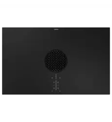
5.1 Structure ...................................................................12
5.2 Operating panel and operating principle ..................12
5.3 Functional principle of the cooktop extractor ..........13
5.3.1 Freely adjustable power control ...............................13
5.3.2 Automatic after-run ...................................................13
5.3.3 Filter service display .................................................13
5.3.4 Interface communication ..........................................13
5.3.5 Safety shut-down .....................................................13
6 Installation 14
6.1 Checking the scope of delivery ................................14
6.2 Tool and aids .............................................................14
6.3 Assembly instructions ...............................................14
6.3.1 Safety clearances ......................................................14
6.3.2 Work surface and kitchen units ................................14
6.3.3 Cooktop air intake ....................................................15
6.4 Cut-out dimensions ...................................................15
6.5 Installing the extraction system ...............................16
6.5.1 Installing the cooktop extractor ...............................17
6.5.2 Preparing to install the substructure module,
silence module and plinth fan ..................................18
6.5.3 Installation – standard set-up ...................................20
6.6 Establishing the power connection
and communication ..................................................21
6.7 Connecting external switch contacts .......................22
6.8 Handover to user ......................................................24
7 Operation 25
7.1 Operating the cooktop extractor ..............................25
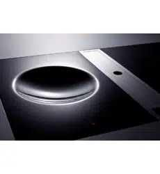
7.1.1 Opening the cover plates ..........................................25
7.1.2 Adjusting the power level .........................................25
7.1.3 Automatic after-run ..................................................25
7.2 Pay attention to the filter service display .................26
7.2.1 Closing the cover plates ...........................................26
8 Cleaning and Maintenance 27
8.1 Cleaning agents ........................................................27
8.2 Cleaning the cooktop extractor ................................27
8.2.1 Removing the cover plates and the stainless steel
grease filter ................................................................27
8.2.2 Cleaning the cover plates and the stainless steel
grease filter ...............................................................27
8.2.3 Installing the cover plates and stainless steel
grease filter ...............................................................28
8.3 Replacing the activated charcoal filter .....................28
9 Troubleshooting 29
10 Decommissioning, disassembly
and disposal 30
10.1 Decommissioning......................................................30
10.2 Disassembly ..............................................................30
10.3 Environmentally-friendly disposal .............................30
11 Warranty, technical service,
spare parts, accessories 31
11.1 Warranty ....................................................................31
11.2 Service .......................................................................31
11.3 Replacement parts ....................................................31
11.4 Accessories ...............................................................31
EN
4
General information
www.bora.com
1 General information
1.1 Target group
These operating and installation instructions apply for the
following target groups:
Target group Requirements
User The appliance can be used by children
aged 8 and above as well as people with
reduced physical, sensory or mental
capacities or a lack of experience and/or
knowledge if they are supervised or have
been instructed how to safely use the
appliance and understand the resultant
risks. Children must be supervised. All
safety and warning information and the
handling instructions in the installation
instructions must be complied with.
Ambitious DIYers Ambitious DIYers can independently
conduct all joinery and installation work
providing they possess the necessary
skills and expertise. They must never
independently establish electricity and
gas connections.
Installation specialists Installation specialists are authorised
to conduct all joinery and installation
work in line with
existing regulations. The
electricity and gas connections must be
certified by a certified engineer for the
applicable trade prior to commissioning.
Electricians The electrical connection may only be
established by a certified engineer.
He/she also assumes responsibility for
the proper electrical installation and
commissioning.
Gas specialists The gas connection may only be
established by certified engineers.
They also assume responsibility for
proper installation and commissioning of
the gas system.
Tab. 1.1 Target groups
INFO BORA Holding GmbH, BORA Vertriebs GmbH
& Co KG, BORA APAC Pty Ltd and BORA
Lüftungstechnik GmbH - hereinafter referred
to as BORA - do not assume any liability for
damage arising from non-adherence to these
documents and from improper assembly! The
electricity and gas connections must be made
by a qualified specialist. Installation must
comply with the valid standards, regulations
and laws. All safety and warning information
and the operating and installation instructions
must be complied with.
1.2 Validity of the operating and
installation instructions
These instructions apply to several device versions. It is
therefore possible that some of the features described do
not apply to your appliance.
1.3 Other applicable documents
These operating and installation instructions are valid
in conjunction with other documents, which must be
adhered to.
Please be sure to adhere to all documents that form part
of the scope of delivery.
INFO BORA accepts no liability for damage caused
by failure to comply with these documents!
Directives
This device meets the following EU/EC directives:
2014/30/EU EMC Directive
2014/35/EU Low Voltage Directive
2009/125/EC Ecodesign Directive
2010/30/EU Energy Consumption Label Directive
2011/65/EU RoHS Directive
2012/19/EU WEEE Directive
EN
5
General information
www.bora.com
1.4 Presentation of information
To make working with these instructions quick and
easy, consistent formatting, numbering, symbols,
safety instructions, terms and abbreviations are used
throughout.
Handling instructions are market with an arrow.
Always carry out handling instructions in the sequence
shown.
Bullet points are indicated by a square bullet point at
the edge of the line.
Bullet point 1
Bullet point 2
INFO Information points out specific points you must
always comply with.
Safety and warning information
The safety and warning information in these instructions
are highlighted with symbols and signal words.
Safety and warning information is structured as follows:
WARNING SYMBOL AND SIGNAL
WORD!
Type and source of the danger
Consequences of non-compliance
Measures to minimise risk
The following applies:
The warning symbol draws attention to the danger.
The signal word indicates the severity of the risk.
Warning sign Signal word Hazard
Danger Indicates an imminent hazardous
situation which could lead to
death or serious injury
if ignored.
Warning Indicates an imminent hazardous
situation which could lead to
death or serious injury if
ignored.
Caution Indicates a potentially hazardous
situation which could lead to slight
or minor injuries if ignored.
— Caution Indicates a situation which could
result in material damage if
ignored.
Tab. 1.2 Meaning of warning symbols and signal words

EN
6
Safety
www.bora.com
2 Safety
2.1 General safety instructions
INFO The appliance complies with the
stipulated safety requirements. The
user is responsible for appliance
cleaning and maintenance as well as
its safe use. Improper use can lead
to personal injury and damage to
property.
The operating and installation instructions
contain important information about
installation and operation. These enable you
to protect yourself against injuries and
prevent damage to the appliance. Contact
details for further information as well as
application and usage questions can be
found on the back of these operating and
installation instructions.
The term device applies to cooktops,
cooktop extractors and cooktops with
cooktops extractors.
Read the operating and installation
instructions fully before using the appliance
for the first time.
Always store the operating and installation
instructions within easy reach so that they
can be accessed if required.
Pass the operating and installation
instructions to the next owner if you sell
the appliance.
Conduct all work extremely attentively and
conscientiously.
Check the appliance for visible damage
when unpacking it.
Do not connect a damaged appliance.
Only use the appliance once all installation
activities are complete. This is the only way
to ensure safe operation.
Make sure that hot hobs are not touched.
Avoid boiling over.
Only operate the cooktop extractor with
BORA cooktops. This particularly applies to
use with BORA gas cooktops.
Switch the device off after use.
Keep pets away from the appliance.
Recirculation mode
INFO When cooking, additional moisture is
released into the ambient air.
INFO In recirculation mode, only a slight
amount of moisture is removed from
the cooking vapour.
When using recirculation mode, ensure a
sufficient supply of fresh air, e.g. by
opening a window.
Ensure a normal and comfortable room
climate (humidity of 45–60%), e.g. by
opening natural ventilation openings or
using domestic ventilation systems.
After every use in recirculation mode,
switch the cooktop extractor to a low level
for about 20 minutes or activate the
automatic after-run function.
Households with children and people with
special needs
The appliance can be used by children aged
8 and above as well as people with reduced
physical, sensory or mental capacities or a
lack of experience and/or knowledge if
they are supervised or have been instructed
how to safely use the appliance and
understand the resultant risks.
Supervise children in the vicinity of the
appliance.
Children must not play with the appliance.
Do not store any items that could be of
interest to children in storage spaces above
or behind the appliance. Children will
otherwise be encourage to climb on the
appliance.
Unauthorised modifications
Unauthorised modifications can cause the
appliance to pose risks.
Do not conduct any modifications to the
appliance.
Cleaning and maintenance
The device must be cleaned regularly. Dirt
can lead to damage or the buildup of odours.
Remove any dirt immediately.
Cleaning and maintenance work must not
be carried out by children unless they are
supervised at all times.
EN
7
Safety
www.bora.com
WARNING!
Risk of injury due to moving fan
wheel!
There is a risk of injury if the fan
wheel turns.
Only install the device with the
power disconnected.
Connect both sides of the fan to
the duct system before
commissioning.
Ensure that the inlet nozzle is
locked before the device is
commissioned for the first time.
CAUTION!
Risk of injury from moving cover flap!
There is a risk of injury when the
electric cover ap moves.
Do not put your hands inside the
cooktop extractor while the cover
flap is moving.
CAUTION!
Touchable parts may become hot!
The cooktop extractor and its
touchable parts are hot when the
cooking zone is switched on and
during the cooling phase.
Do not place any items on the
cooktop.
Please use suitable tools
(pot holders, oven gloves).
CAUTION!
Damage caused by objects or
paper suctioned in!
Small and light items, such as
cleaning cloths made from material
or paper, can be suctioned into
the cooktop extractor. This can
damage the fan or impair the exhaust
performance.
Do not store any items or paper on
the cooktop extractor.
CAUTION!
Damage caused by grease and dirt
deposits!
Grease and dirt deposits can stop the
cooktop extractor from functioning
properly.
Never use the cooktop extractor
without a stainless steel grease filter.
Do not use steam cleaners. The steam can
cause a short-circuit on live parts and
cause damage to property (see Cleaning
and maintenance section).
Make sure no water penetrates inside the
device when cleaning. Only use a slightly
damp cloth. Never spray water on the
device. Water ingress can cause damage!
2.2 Safety instructions – operation
Cooktop extractor
DANGER!
Risk of smoke inhalation!
Using a replace that depends on the
air in the room produces combustion
gases.
If the cooktop extractor is used in
conjunction with a replace that
depends on the air in the room, toxic
combustion gases (carbon monoxide)
can be extracted from the chimney
or outlet duct into the living area.
Make sure that there is always a
sufficient air supply.
DANGER!
Fire risk from flambéing!
While the cooktop extractor is
working, it sucks up grease from
cooking. Flambéing food can cause
the grease to catch re.
Clean the cooktop extractor
regularly.
Never work with a naked flame
while the cooktop extractor is
running.
DANGER!
Fire risk from fat deposits!
If the stainless steel grease lter is
not cleaned regularly, this can lead to
increased levels of grease in it. This
increases the re risk.
Clean and replace the filter at
regular intervals.
EN
8
Safety
www.bora.com
DANGER!
Risk of electric shock!
Incorrect stripping of the connection
cable to external switching devices
results in a risk of electric shock.
Ensure that the connection cable
is secured with the strain relief
clamp within the universal control
unit.
Ensure that the stated stripping
lengths are adhered to.
Check the appliance for visible damage
before installing it.
Do not install damaged devices.
A damaged device is a hazard.
Repair work must only be carried out by
specialists authorised by the manufacturer.
2.4 Safety instructions –
disassembly and disposal
The device must only be disassembled by
trained specialists who are familiar with and
comply with the standard national regulations
and supplementary regulations of the local
utility companies.
Work on electrical components must only be
conducted by trained electrical personnel.
DANGER!
Risk of electric shock!
Incorrectly disconnecting the
appliance from the mains results in a
risk of electric shock.
Securely disconnect the appliance
from the mains using LS switches,
fuses, automatic circuit breakers
or contactors.
Use an authorised measuring
device to ensure that there is no
power to the appliance.
DANGER!
Risk of asphyxiation!
Packaging components (e.g. lm,
polystyrene) can be life-threatening
for children.
Store all packaging components
out of reach of children.
Dispose of the packaging properly
and immediately.
2.3 Safety instructions – installation
The device must only be installed and
assembled by trained specialists who are
familiar with and comply with the standard
national regulations and supplementary
regulations of the local utility companies.
Work on electrical components must be
conducted by trained electrical personnel.
The electrical safety of the appliance is only
guaranteed if it is connected to a protective
conductor system that has been installed in
line with regulations. Ensure that this basic
safety precaution is met.
Cooktop extractor
DANGER!
Risk of poisoning from combustion
gases!
If the cooktop extractor is used in
exhaust mode, it draws in air from
the room in which it is installed as
well as from neighbouring rooms. If
there is insucient air supply, low
pressure will occur. Toxic gases
could be drawn out of the replace
that depends on the air in the room
or extraction ducting and back into
the room.
Make sure that there is always a
sufficient air supply.
Only use approved and tested
switchgear (e.g. window contact
switch, low-pressure monitor)
and have them approved by
authorised specialists (certified
chimney-sweep).
DANGER!
Risk of electric shock!
The control unit can contain residual
charge and cause an electric shock.
Never touch exposed contacts on
t
he control unit.
EN
9
Safety
www.bora.com
2.5 Safety instructions – spare parts
WARNING!
Risk of injury and damage to
property!
Incorrect components can lead to
personal injury or damage to the
appliance. Modications, additions or
alterations to the appliance can lead
to safety risks.
Only use original spare parts for
repairs.
2.6 Intended use
The device cannot be used at altitudes above
2000 m (metres above sea level).
The device is designed exclusively for the
preparation of food in private households.
This appliance is not intended for:
Outdoor use
Installation in vehicles
Heating rooms
Use in non-stationary installation sites
(e.g. on ships)
Use with an external timer or a separate
remote control system (remote operation)
Any use other than that specified in these
operating and installation instructions or any
use that goes beyond that which is described
here is classed as unintended. BORA does not
assume any liability for damages caused by
improper use or incorrect operation.
All misuse is prohibited!
INFO BORA Holding GmbH, BORA Vertriebs
GmbH & Co KG, BORA APAC Pty Ltd
and BORA Lüftungstechnik GmbH do
not assume any liability for damage
arising from non-adherence
to the
safety and warning information.
EN
10
Technical data
www.bora.com
3 Technical data
Parameter Value
Supply voltage 220 - 240 V
Frequency 50/60 Hz
Power consumption 170 W
Dimensions
(width x depth x height)
90 x 515 x 140 mm
Weight
(incl. accessories/packaging)
11.0 kg
Extractor
Power levels 1 - 5
Plinth fan
Maximum flow volume 608.8 m³/h
Maximum pressure 597 Pa
Dimensions
(width x depth x height)
370 x 358 x 100 mm
Exhaust opening dimensions
(width x depth x height)
222 x 40 x 89 mm
Duct system
Total height adjustable from - to 900 - 1050 mm
Total depth adjustable from - to 560 - 710 mm
Tab. 3.1 Technical data
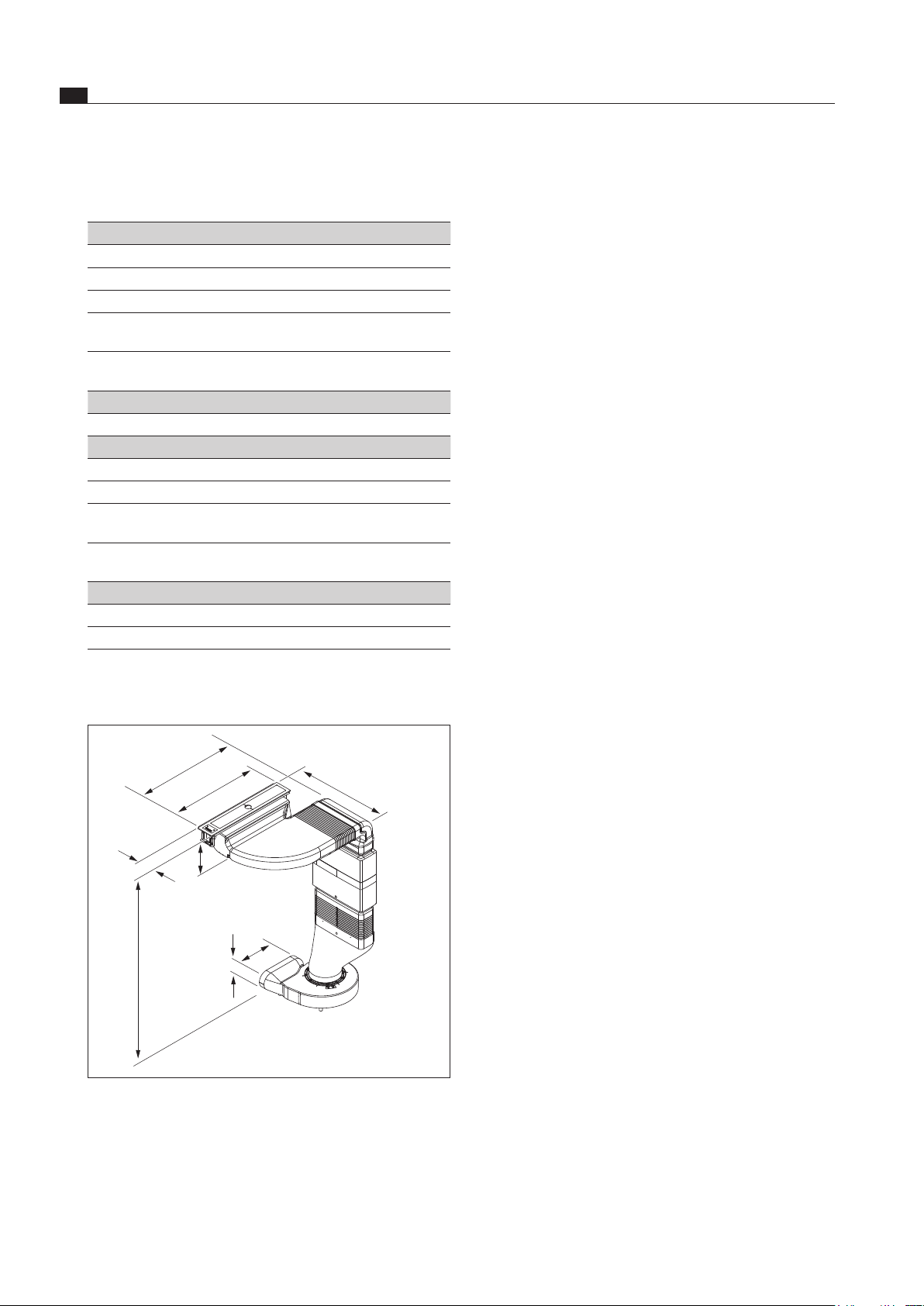
Device dimensions
515
560 - 710
90
>140
222
89
900 - 1050
460
Fig. 3.1 Device dimensions
EN
11
Energy label
www.bora.com
4 Energy label
Product description
Classic cooktop extractor system with ULS plinth fan
CKASE
Operating mode
Exhaust air
Energy consumption
Value EN standard
Annual energy consumption (AEC
hood
) 24 kWh/a 61591
Energy efficiency class
A++ 61591
Flow volume
Fluid dynamic efficiency (FDE
hood
) 38.4 61591
Fluid dynamic efficiency class
A 61591
Lighting
Lighting efficiency (LE
hood
) * lx/Watt *
Lighting efficiency class
* *
Grease filtering
Level 5 maximum (GFE
hood
) 47% 61591
Class level 5 normal
F 61591
Flow volume
Air flow level 1 minimum
224 m³/h 61591
Air flow level 5 maximum (Q
max
) 609 m³/h 61591
Sound power level
Level 1 minimum
46 dB(A) 60704-2-13
Level 5 maximum
67 dB(A) 60704-2-13
Sound pressure level (additional details)
Level 1 minimum
33 dB(A) **
Level 5 maximum
55 dB(A) **
Details according to 66/2014
Power consumption in off mode (P
O
) < 0.5 W 61591
Time increase factor
0.6 61591
Energy efficiency index (EEI
hood
) 31.7 61591
Air flow rate at the best efficiency point (Q
BEP
) 280.8 m³/h 61591
Pressure at the best efficiency point (P
BEP
) 536 Pa 61591
Electric power input at the best efficiency point (W
BEP
) 109 W 61591
Tab. 4.1 Energy label information
* This specification is not applicable for this product.
** The sound pressure level has been determined from a distance of 1 m (distance-dependent level recording) on the
basis of the sound power level established in EN 60704-2-13.
EN
12
Device description
www.bora.com
5 Device description
Observe all safety and warning information during operation
(see the Safety section).
The cooktop extractor system has the following features:
Touch-operated power control
Electronic power control (5 power levels)
Automatic after-run
Filter service display
Interface communication
Safety shut-down
Integrated silencer (silence module)
Rubberised device feet
Depending on the model you purchased, the cooktop
extractor system can be operated as an exhaust air or an
recirculating air version.
Exhaust mode
The air extracted from the cooktop is cleaned by the
stainless steel grease filter and released outside through
a duct system.
The exhaust air must not be expelled into:
a smoke or exhaust gas flue that is in operation
a shaft used for the aeration of rooms where
fireplaces are installed.
If the exhaust air is to be directed into a smoke or
exhaust gas flue that is not in use, the installation must
be checked and approved by the responsible heating
engineer.
Recirculation mode
The air suctioned away by the cooktop is purified by the
grease filter and an activated charcoal filter and fed back
into the room in which the appliance is installed.
An activated charcoal filter must be used to prevent
odours in recirculation mode, . For hygiene and health
reasons, the activated charcoal filter must be replaced
at the recommended intervals (see the Cleaning and
maintenance section).
INFO In recirculation mode, ensure sufficient
ventilation and aeration to discharge humidity.
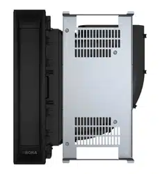
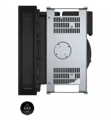
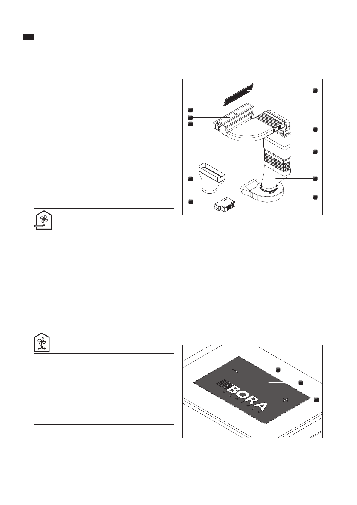
5.1 Structure
1
10
9
2
3
4
5
8
7
6
Fig. 5.1 Cooktop extractor system
[1] Stainless steel grease filter
[2] Substructure module
[3] Silence module
[4] Curved transition piece
[5] Universal plinth fan
[6] Classic control unit
[7] Straight transition piece (optimal)
[8] Touchscreen operating panel with fan display
[9] Cooktop extractor cover plate
[10] Cooktop extractor frame
[11] Protective grid (not shown)
5.2 Operating panel and operating
principle
c
1
2
3
Fig. 5.2 Touchscreen operating panel with fan display
[1] Minus button
[2] Fan display
[3] Plus button
EN
13
Device description
www.bora.com
5.3.4 Interface communication
The internal interface can be used for extended control
options. This has a Home-In and a Home-Out contact
(see the Installation section).
The Home-In contact can be used for the incoming
signal from external switch devices (e.g. window
contact switch).
The Home-Out contact can be used to control
external installations.
5.3.5 Safety shut-down
The cooktop extractor switches off automatically if no
buttons are pressed for 120 minutes.
Unit Display Meaning
Fan display
0
Fan off
1
-
5
Power levels
E
Interface display
F
Filter service display
n
Automatic after-run
Tab. 5.1 Display meanings
Touch control
The operating panel is fitted with electronic sensor
buttons and display panels. The sensor buttons respond
to finger contact.
The device is operated by touching the corresponding
sensor button with your finger. Keep your finger pressed
on the sensor button until the display changes as desired.
5.3 Functional principle of the
cooktop extractor
5.3.1 Freely adjustable power control
The power levels are controlled using the
and
buttons on the touchscreen operating panel.
5.3.2 Automatic after-run
The cooktop extractor continues to run at a lower level
n
and switches off automatically after 20 minutes.
5.3.3 Filter service display
The filter service display becomes active after the cooktop
extractor has operated for 200 hours. The activated
charcoal filter has reached the end of its service life
(with recirculation only) and the stainless steel grease
filter needs to be thoroughly cleaned.
A flashing
F
is displayed in the filter service display.
The display goes out as soon as a power level has been
selected.
The filter service display is shown every time the
cooktop extractor is switched on and remains active
until the filter has been changed and the filter service
display has been reset (see the Operation section).
The cooktop extractor can still be operated without
limitations.
EN
14
Installation
www.bora.com
6 Installation
Observe all safety and warning information (see the
Safety section).
INFO The device must not be installed above cooling
devices, dishwashers, stoves, ovens, washing
machines or dryers.
INFO The contact surfaces of the worktops and wall
sealing strips must be made of a heat-resistant
material (up to approx. 100 °C).
INFO Worktop cut-outs must be moisture-sealed
using suitable means or, where necessary,
fitted with a thermal insulator.
6.1 Checking the scope of delivery
Name Quantity
Cover plates 2
Operating and installation instructions 1
Sealing tape for the cooktop extractor 1
Stainless steel grease filter 1
Height adjustment plate set 1
Cooktop extractor frame 1
CAT 5 communication cable 1
Lenshead screws 4
Power supply cable 1
Protective grid 1
Silence module 1
UDB Universal sealing tape 1
ULS Universal plinth fan 1
CSEE Classic control unit 1
Substructure module 1
Curved transition piece 1
Straight transition piece 1
Tab. 6.1 Scope of delivery
Check the scope of delivery for damage and make
sureTab. 6.1omplete (see tab. 6.1).
If there are any missing or damaged parts, please
notify BORA After Sales Service.
Do not under any circumstances install parts which are
damaged.
Dispose of transport packaging in the proper manner
(see the Decommissioning, disassembly and disposal
section).
6.2 Tool and aids
The following tools are required to correctly install the
cooktop extractor:
Pencil
Tape measure
Phillips screwdriver Z2
Black, heat-resistant silicone sealant
Fine saw
6.3 Assembly instructions
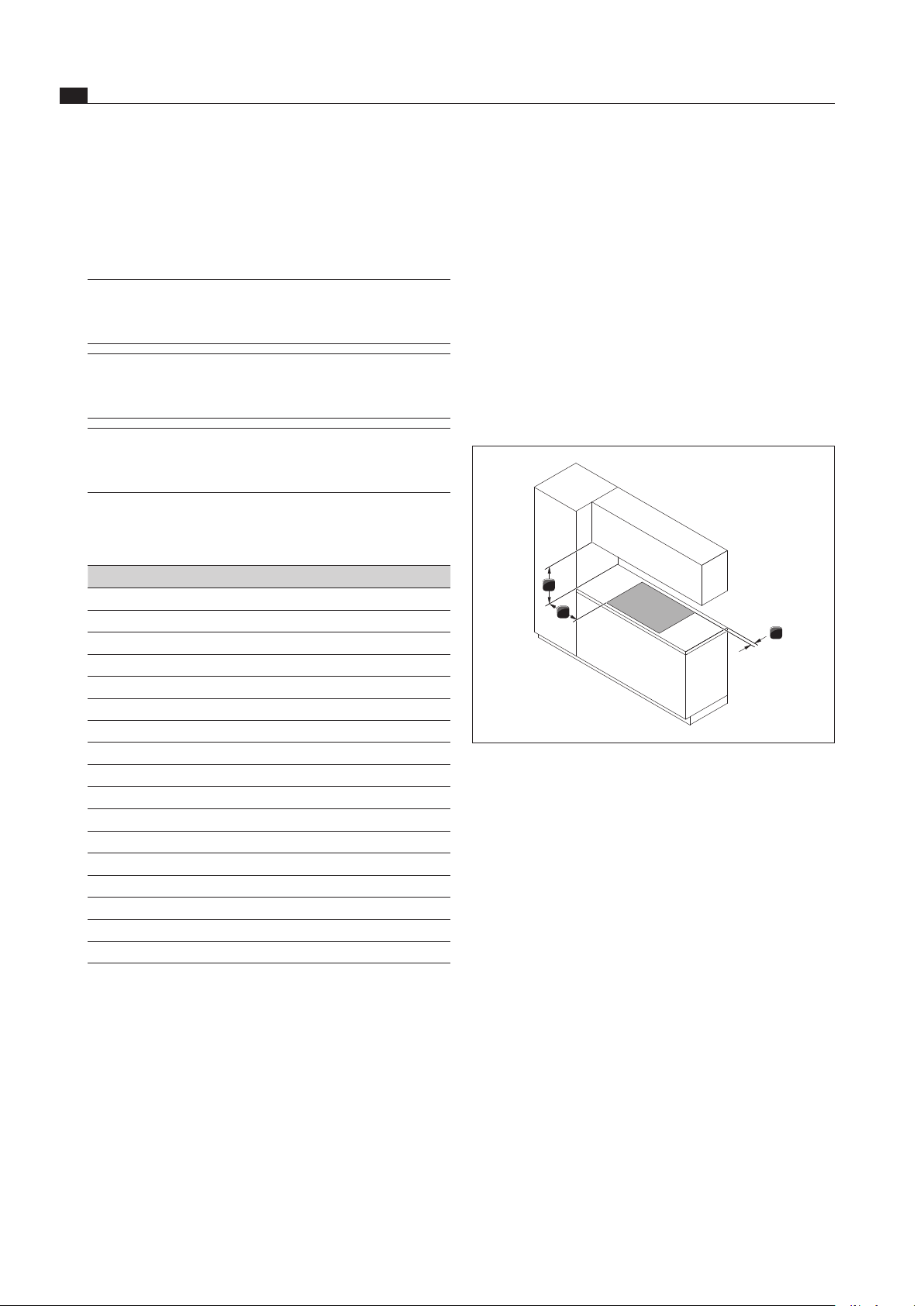
6.3.1 Safety clearances
1
3
2
Fig. 6.1 Recommended minimum clearances
Maintain the following safety clearances:
[1] Rear minimum clearance of 50 mm between the worktop
cut-out and the rear corner of the worktop.
[2] Minimum clearance of 50 mm from the left and right of
the worktop cut-out to the adjacent cabinet or wall. For
ergonomic reasons and to ensure efficient cooktop extraction,
a minimum clearance of 300 mm is recommended.
[3] Minimum clearance of 600 mm between the worktop
and the wall unit. A minimum clearance of 1000 mm is
recommended for ergonomic reasons.
6.3.2 Work surface and kitchen units
Create the worktop cut-out taking the specified cut-out
dimensions into account.
Make sure that the cutting surfaces of the worktops
are properly sealed.
Observe the instructions provided by the worktop
manufacturer.
Cross bars on the unit in the area of the worktop cut-
out may need to be removed.
Cable protection (false floor) should be mounted
below the appliances. This needs to be removable for
maintenance work.
The drawers and/or shelves in the floor unit must be
removable.
EN
15
Installation
www.bora.com
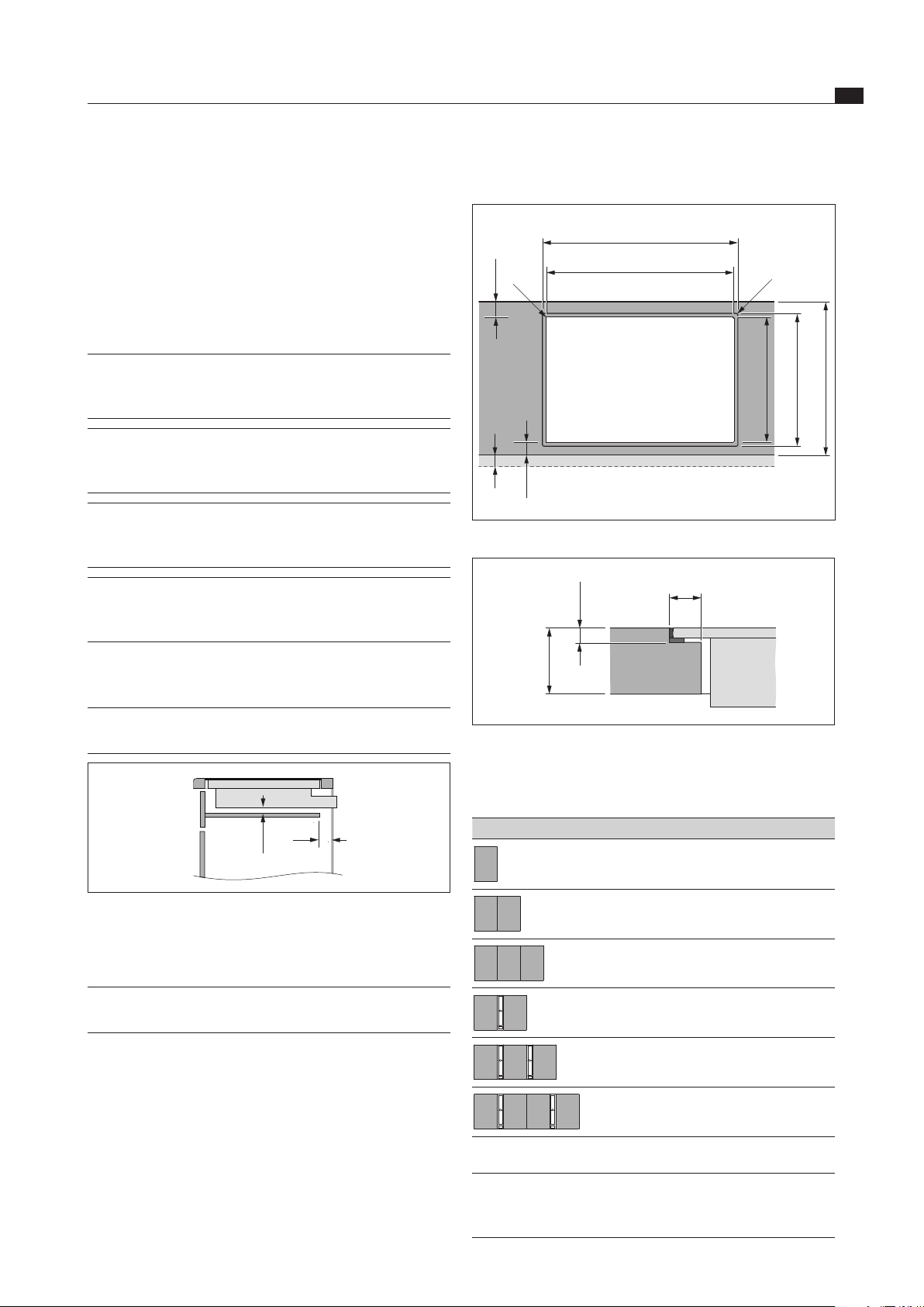
Flush installation
x
≥ 50
A ±2
B ±2
519 ±2
≤ R5
≤ R5
≥ 50
495 ±2
≥ 600
Fig. 6.3 Flush installation
5 +0,5
12
10 – 40
Fig. 6.4 Groove dimensions cut-out
Cut-out dimensions when installing cooktops only or cook-
tops and the BORA cooktop extractor alongside each other:
Cooktops/cooktop extractor A in mm B in mm
1/0 344 320
2/0 685 661
3/0 1026 1002
2/1 776 752
3/2 1208 1184
4/2 1549 1525
Tab. 6.2 Cut-out dimensions
INFO If the induction glass ceramic wok is used, the
groove dimensions must be increased to 7 mm
for flush installation.
A return flow aperture > 500 cm
2
is required in the
kitchen units for recirculation appliances (e.g. by
shortening the plinth boards or using suitable slatted
plinths).
6.3.3 Cooktop air intake
The components in the cooktop which generate heat are
automatically cooled. The warm air is extracted by fans
(cold air flow).
INFO In order to retain the full functionality of
the cooktop in the long term, there must be
sufficient ventilation underneath the cooktop.
INFO The performance of the cooktop is impaired or
the cooktop overheats if the warm air below
the cooktop cannot escape.
INFO If the cooktop overheats, performance
is reduced or the cooktop switches off
completely (see Overheating protection).
INFO For sufficient air intake, an opening cross-
section in the kitchen units of at least 50 cm
2
is recommended.
Ensure there is sufficient ventilation underneath the
cooktop.
INFO The cable protection (false floor) must not
prevent sufficient ventilation.
> 20
50
Fig. 6.2 Side view of the cable protection and ventilation
6.4 Cut-out dimensions
INFO All dimensions from the front edge of the
front cover.
Please note the worktop overhang x when creating
the worktop cut-out. Applies to flush installation and
surface mounting.
EN
16
Installation
www.bora.com
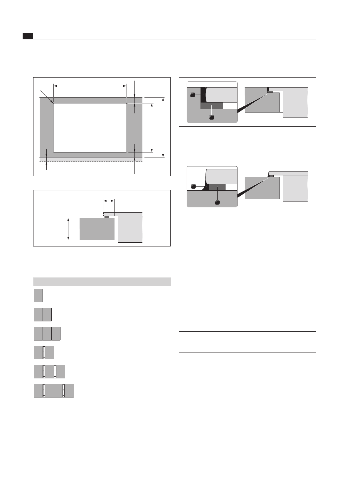
Attaching the sealing tape
1
2
Fig. 6.7 Sealing tape with ush installation
[1] Black, heat-resistant silicone sealant
[2] Sealing tape
2
1
Fig. 6.8 Sealing tape with surface mounting
[1] Black, heat-resistant silicone sealant
[2] Sealing tape
With surface mounting, attach the enclosed sealing
tape [2] to the underside of the device before installing
it. Do not leave any gaps.
With flush installation, attach the enclosed sealing tape
to the horizontal cutting edge in the worktop cut-out,
even if you seal the cooktop with a silicone sealant [1]
or similar.
Stick the supplied nameplate (adhesive label) to the
back of your operating and installation instructions.
6.5 Installing the extraction system
INFO Clearance of one millimetre should be planned
between the built-in appliances.
INFO A clearance of two millimetres should be
planned around the built-in appliances.
Surface mounting
x
B ±2
≤ R5
≥ 50
495 ±2
≥ 600
≥ 50
Fig. 6.5 Surface mounting
10
10 – 40
Fig. 6.6 Surface mounting cut-out
Cut-out dimensions when installing cooktops only or cook-
tops and the BORA cooktop extractor alongside each other:
Cooktops/cooktop extractor B in mm
1/0 320
2/0 661
3/0 1002
2/1 752
3/2 1184
4/2 1525
Tab. 6.3 Cut-out dimensions
EN
17
Installation
www.bora.com
> 600
> 50
> 900
Fig. 6.12 Device installation dimensions
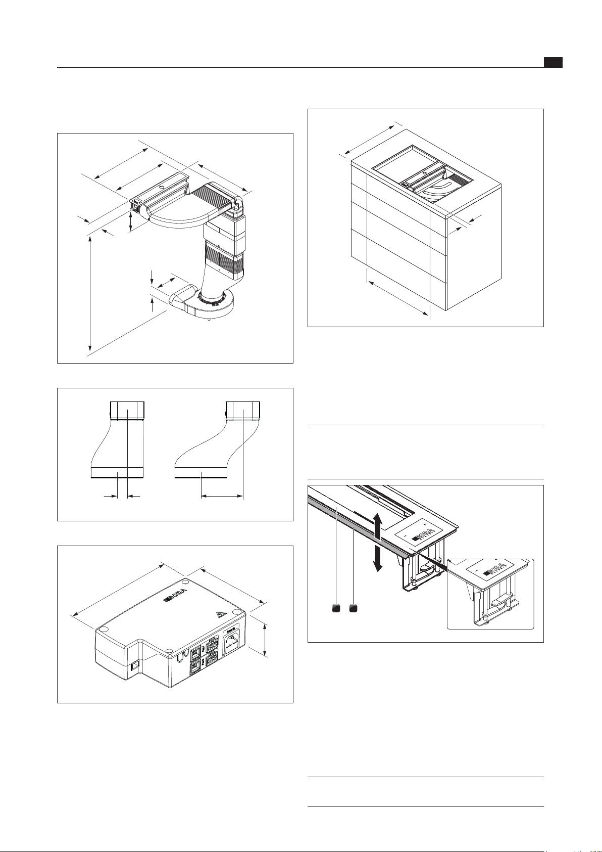
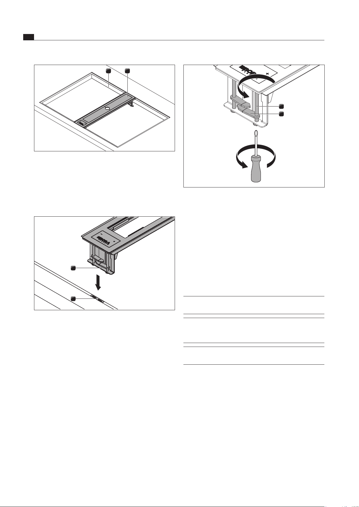
6.5.1 Installing the cooktop extractor
Preparing the cooktop extractor frame for
installation in conjunction with the induction
glass ceramic wok
INFO To install the induction glass ceramic wok,
the rail on the left hand side of the cooktop
extractor frame must be removed due to the
6 mm thick glass ceramic.
21
Fig. 6.13 Preparing the cooktop extractor frame
[1] Cooktop extractor frame
[2] Left hand side rail
Use a pair of pliers to remove the rail from the left
hand side of the cooktop extractor frame by carefully
bending it up and down.
Installing the cooktop extractor frame
INFO The cooktop extractor’s substructure module
can only be installed sloping down to the right.
Installation dimensions
515
560 - 710
90
>140
222
89
900 - 1050
460
Fig. 6.9 Device dimensions with curved transition piece
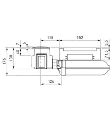
30 124,50
Fig. 6.10 Oset with transition pieces
187
60
128
Fig. 6.11 Control unit installation dimensions
EN
18
Installation
www.bora.com
1
2
Fig. 6.16 Securing the cooktop extractor
[1] Tensioning screw
[2] Clamp
Turn the four clamps [2] under the worktop.
Tighten the clamp screws [1] with max. 10 Nm.
Check that the cooktop extractor frame is positioned
correctly.
Once all of the installation work is complete, seal the
devices with black, heat-resistant silicone sealant.
6.5.2 Preparing to install the substructure
module, silence module and plinth fan
INFO The floor unit must not be supported on the
plinth fan housing.
INFO For correct installation, the slide-in units of the
base cabinet must be shortened depending on
the installation situation.
INFO The plinth fan must only be installed
horizontally.
Now adapt the cooktop extractor system to the
worktop height by shortening the silence module at the
cut marks using a fine saw.
1
2
Fig. 6.14 Installing the cooktop extractor
[1] Cooktop cut-out
[2] Cooktop extractor frame
Insert the cooktop extractor frame [2] in the middle of
the relevant worktop cut-out.
Precisely position the cooktop extractor.
1
2
Fig. 6.15 Height adjustment plates
[1] Height adjustment plate
[2] Cooktop extractor frame
If applicable, insert the height adjustment plates [1].
EN
19
Installation
www.bora.com
1
2
3
Fig. 6.19 Shortening the substructure module
[1] Substructure module
[2] Cut marks
[3] Fine saw
Prepare the plinth fan by attaching the sealing tape
depending on the installation situation.
Secure the sealing tape to the inlet nozzle.
Fig. 6.20 Sealing tape position for installation with a round duct
Secure the sealing tape on the outlet nozzle.
Fig. 6.21 Sealing tape position for installation with a transition
piece (shallow duct)
1
2
3
Fig. 6.17 Shortening the silence module
[1] Silence module
[2] Cut marks
[3] Fine saw
Now place the (curved or straight) transition piece and
the silence module together on the plinth fan.
2
3
5
4
1
Fig. 6.18 Assembly
[1] Protective grid
[2] Silence module
[3] Transition piece (curved or straight)
[4] Universal plinth fan inlet nozzle
[5] Universal plinth fan
Saw out the necessary cut-outs for the ducting in the
rear panel of the floor unit.
Depending on the installation situation, adjust the
levelling feet on the floor unit as necessary.
Now adapt the substructure module to the available
depth of the worktop by shortening the substructure
module at the cut marks using a fine saw.
EN
20
Installation
www.bora.com
Push the substructure module [2] into the silence
module [3].
INFO Never place strain on the cooktop extractor
frame when installing the substructure module.
This will deform the cooktop extractor frame.
Connect the substructure module [2] to the cooktop
extractor frame [1] by carefully pressing the
substructure module [2] upwards into the relevant
cooktop extractor frame brackets [1]. The module
should audibly click into place on each of the long
sides of the extractor frame to indicate that it has been
correctly connected.
click
click
click
click
Fig. 6.23 Attaching the substructure module
Use the sealing tape (UDB) provided to adhere the
substructure module [2] to the silence module [3].
Place the control unit [8] in the plinth area.
INFO Position the plinth fan and the control unit in
such a way that they are easily accessible and
removable for maintenance work.
The maximum exhaust air duct length is 6 m.
The minimum cross-section of the air ducts must be
176 cm². This corresponds to a round pipe with a
diameter of 150 mm.
For the ducting, only use stable duct elements with
smooth pipe interiors. Do not use flexible or fabric
tubes.
The exhaust air must be directed outside or to the
recirculation unit through appropriate ducts.
For further planning examples and notices, please see
the ventilation handbook (not included in the scope of
delivery).
INFO When attaching the sealing tape, ensure that
an airtight seal with the connection duct piece
is created when the tape is compressed.
6.5.3 Installation – standard set-up
1
2
3
4
5
6
8
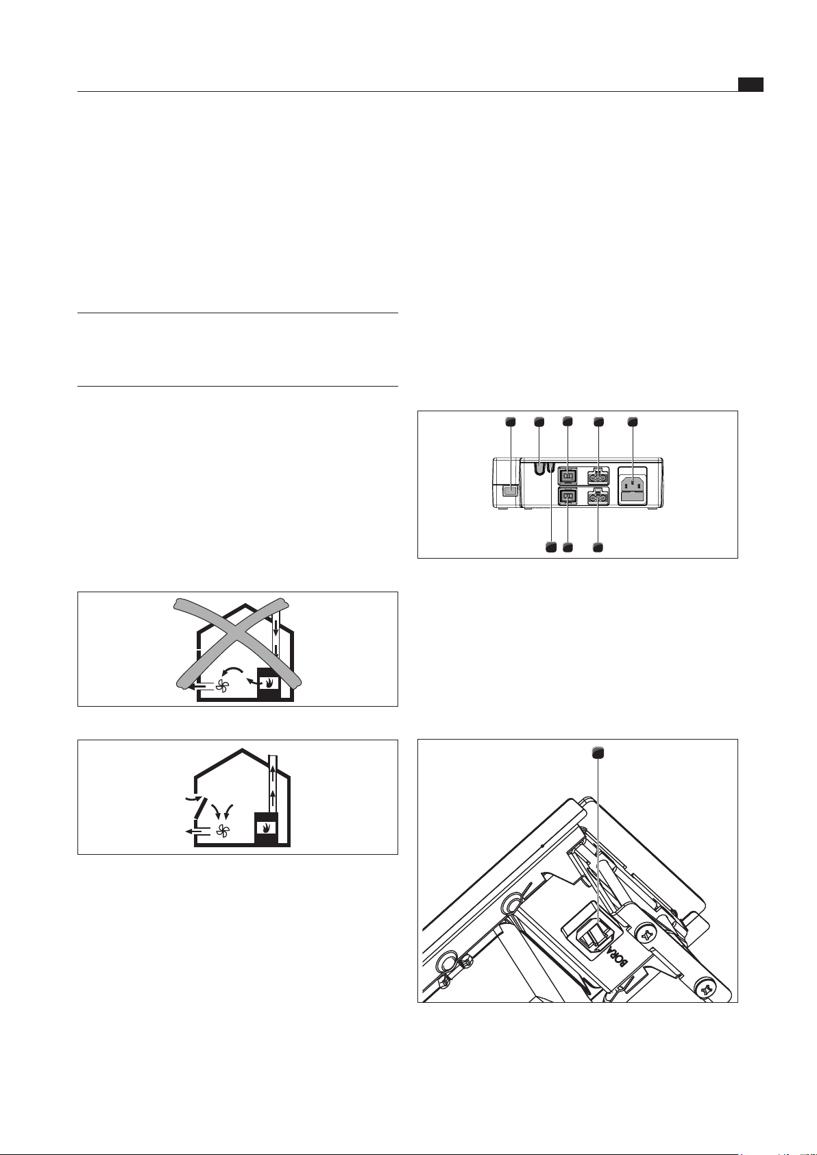
Fig. 6.22 Standard set-up
[1] Cooktop extractor
[2] Substructure module
[3] Silence module
[4] Transition piece (curved or straight)
[5] Universal plinth fan
[6] Air duct or recirculation unit
[7] Protective grid (not visible)
[8] Control unit
Position the plinth fan [5].
To facilitate positioning, the inlet nozzle on the plinth
fan can be removed. To do this, please see the
assembly instructions for the ULS universal plinth fan.
Push the transition piece [4] onto the inlet nozzle of
the plinth fan [5].
You can also use the sealing tape provided (UDB) to
adhere the connections together.
Push the silence module [3] onto the transition piece
[4].
Tape the transition piece [4] to the silence module [3].
INFO To secure the silence module, this must to
screwed to the transition piece to relieve the
strain on the substructure module.
Now screw together the silence module [3] and the
transition piece [4].
Insert the protective grid [7] into the upper opening on
the silence module [3].
EN
21
Installation
www.bora.com
6.6 Establishing the power
connection and communication
Observe all safety and warning information (see the
Safety section).
Observe all national and regional laws and regulations
as well as the supplementary regulations of the local
utility companies.
The plug for the power supply must be accessible
following installation.
If the power supply cable has been damaged this must
be replaced.
Connecting the control unit and fan to the
cooktop extractor
86
4
2
1
75
3
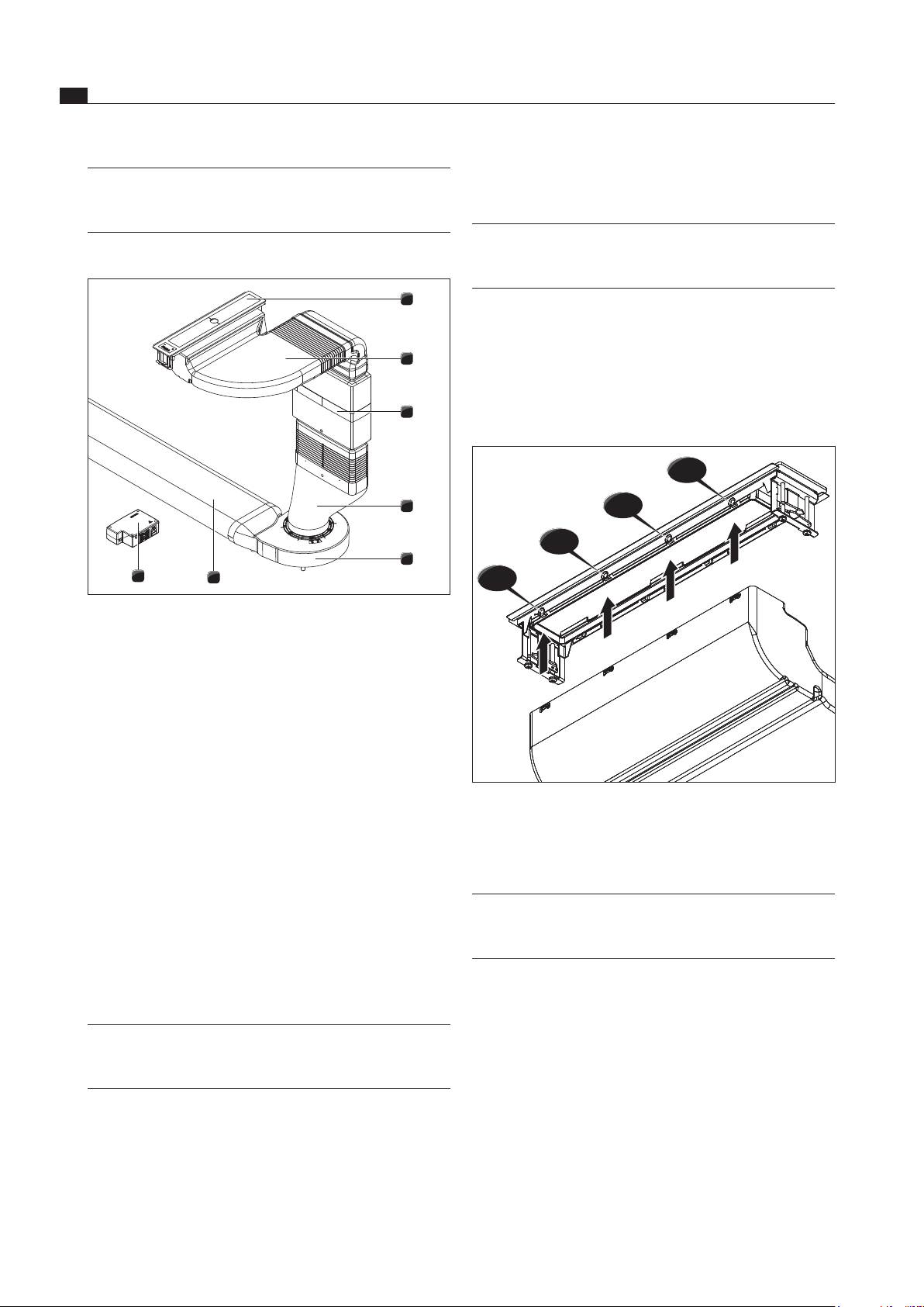
Fig. 6.26 Connections on the control unit
[1] CAT 5 communication cable
[2] Home Out
[3] Home In
[4] Fan 1 control line
[5] Fan 2 control line
[6] Fan 1 power supply cable
[7] Fan 2 power supply cable
[8] Power supply cable with microfuse
1
Fig. 6.27 CAT 5 communication cable connection
Connect the CAT 5 communication cable between the
cooktop extractor connection [1] and the control unit
[1].
Installing the additional fan
Install the additional fan in the exhaust duct.
Ensure that a minimum clearance of 300 cm is
maintained between the fan units.
Only use BORA universal fans with your BORA cooktop
extractor system.
Operating the cooktop extractor with a
fireplace that depends on the air in the room
INFO National and regional laws and regulations
must be observed with regard to the exhaust
duct design. A sufficient air supply must be
ensured.
Fireplaces that depend on the air in the room (e.g. gas,
oil, wood or coal-fired heaters, continuous-flow water
heaters, instantaneous water heaters) draw in air from
the room in which they are installed and release the
exhaust fumes into the outside air via an exhaust system
(e.g. chimney).
If the cooktop extractor is used in exhaust mode, it draws
in air from the room in which it is installed as well as from
neighbouring rooms. If the air supply is insufficient, low
pressure will occur. Toxic gases could be drawn out of the
chimney or extraction ducting and back into the room.
Fig. 6.24 Exhaust air installation – not permitted
Fig. 6.25 Exhaust air installation – correct
If simultaneously operating both a fireplace and the
cooktop extractor in the same room, ensure that:
the maximum low pressure is 4 Pa (4 x 10⁻⁵ bar);
a safety device (e.g. window contact switch, low
pressure warning device) is used to ensure that a
sufficient supply of fresh air is guaranteed;
the exhaust air is not be ducted into a chimney that
is used for exhaust gases of devices operated with
gas or other combustibles;
the installation is checked and approved by an
authorised certified engineer (e.g. heating engineer).

EN
22
Installation
www.bora.com
The following switch contacts can be used:
Contact Function Connection
Home In Cooktop extractor on/off connection
for external switch contact (contact
closed: cooktop extractor on)
24V DC
100 mA
Home Out Electrically isolated contact for
controlling external devices depending
on the operating status of the cooktop
extractor (cooktop extractor on:
contact closed)
Maximum
250 VAC/
30 VDC,
2.5 A
Tab. 6.4 Switch contacts
INFO The Home In contact can be used for external
safety devices (e.g. window contact switches).
If the switch is open, the cooktop extractor is
out of operation.
Ensure that the control unit is disconnected from the
power supply.
Preparing the universal control unit
Remove the screws from the control unit.
Lift up the cover.
1
2
4
3
Fig. 6.29 Open the control unit’s cover
[1] Cover
[2] Electronic unit
[3] Base unit
[4] Switch contact clamp
INFO The electronic unit [2] can contain residual
charge. You must therefore be careful not to
touch the exposed contacts on the electronic
unit!
1
2
Fig. 6.28 Connection plug for the plinth fan
[1] Connection plug for the plinth fan control line
[2] Connection plug for the plinth fan power supply cable
Connect the plinth fan’s control line [1] to the control
unit [4].
Connect the plinth fan’s power supply cable [2] to the
control unit [6].
Release the power supply cable
To release the power supply cable [2] from the control
unit [6] you need a small flathead screwdriver.
Disconnect the control unit’s power supply cable from
the power supply [8].
Make sure that there is no power to the appliance.
Use the flathead screwdriver to loosen the lock on the
power supply cable’s plug.
To do this, insert the flathead screwdriver into the gap
in the socket.
Press the lock down gently.
Use the flathead screwdriver to gently lever the power
supply cable’s plug out of the control unit’s socket.
Now disconnect the power supply cable from the
socket.
Check the plug and the socket for damage.
Do not use damaged components.
Contact your BORA specialist supplier to replace any
damaged components.
Connecting an additional fan
Connect the fan’s control line [1] to the control unit
[5].
Connect the fan’s power supply cable [2] to the control
unit [7].
Check all the plug connections to ensure that they are
secure.
6.7 Connecting external switch
contacts
INFO The Home In and Home Out communication
connections must only be connected by a
certified specialist. The specialist also assumes
responsibility for the proper installation and
commissioning.
When using Home In and Home Out, you will require the
relevant documents for the external switching devices in
order to ensure safe device connection and operation.
EN
23
Installation
www.bora.com
6
5
3
2
1
4
9
UFH
35
120
20
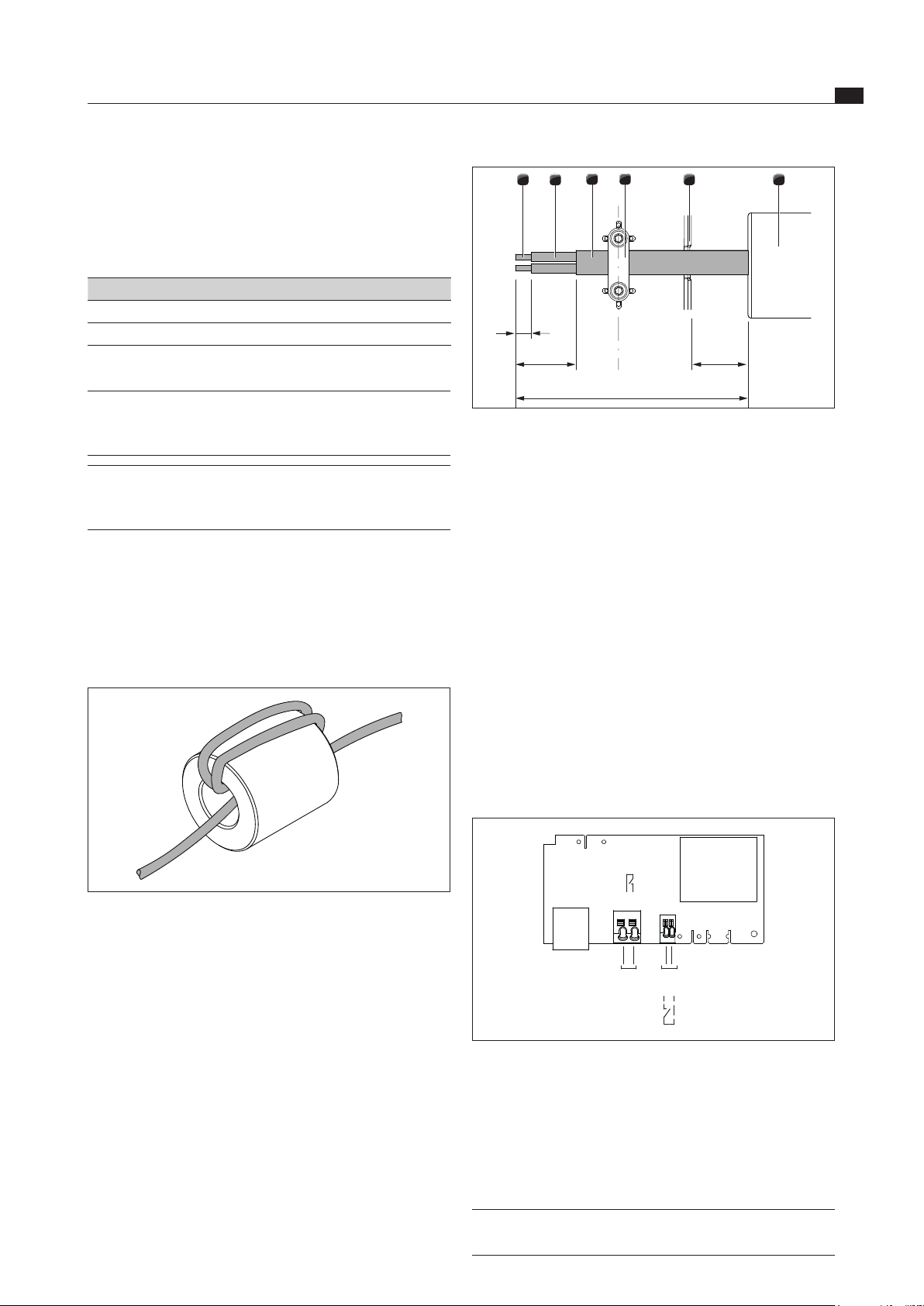
Fig. 6.31 Stripping lengths and assembly position of the
connection cable in the control unit
[1] Stripped wire end
[2] Insulated wire
[3] Jacketed cable
[4] Strain relief clamp
[5] Cable feed snap-out element
[6] Universal ferrite sleeve (UFH)
Please adhere to the maximum stripping length of
9 mm on the stripped wire end [1].
Please adhere to the maximum stripping length of
26 mm on the insulated wire [2].
Installing the external switching device
Depending on the type of switching device, connect the
connection cables to either the Home In or the Home Out
connection clamp.
Adhere to the connection diagram when connecting
Home In and Home Out.
Home
In
Home
Out
X 7.1
X 7.2
X 6.1
X 6.2
Fig. 6.32 Connection diagram for the external switch contacts
Connect the cable for the relevant contact to the
switch contact clamp [4] in accordance with the
relevant connection diagram (see fig. Connection
diagram for the external switch contacts).
In order to connect the Home In interface, the installed
bridge must be removed.
INFO The Home In contact must be bridged if this is
not used (bridged on delivery).
Preparing connection cables for external
switching devices
Use connection cables of the following types and from
the following manufacturer to connect external switching
devices.
Contact Connection cable
Home In H03VV-F 2x0.5mm²
Home Out H03VVH2-F 2x0.75mm²
Tab. 6.5 Connection cable
INFO The connection cable is only designed for
indoor use in buildings, private households,
kitchens or offices!
INFO The overall length of the connection cable for
external switching devices must not exceed
10 m!
For reasons of electromagnetic compatibility, all
connection cables from external switching devices must
be filtered with a ferrite sleeve. This is not included in the
scope of delivery.
Use the order code UFH (universal filter sleeve) to
order the filter sleeve from your specialist supplier or
contact BORA via the website at www.bora.com.
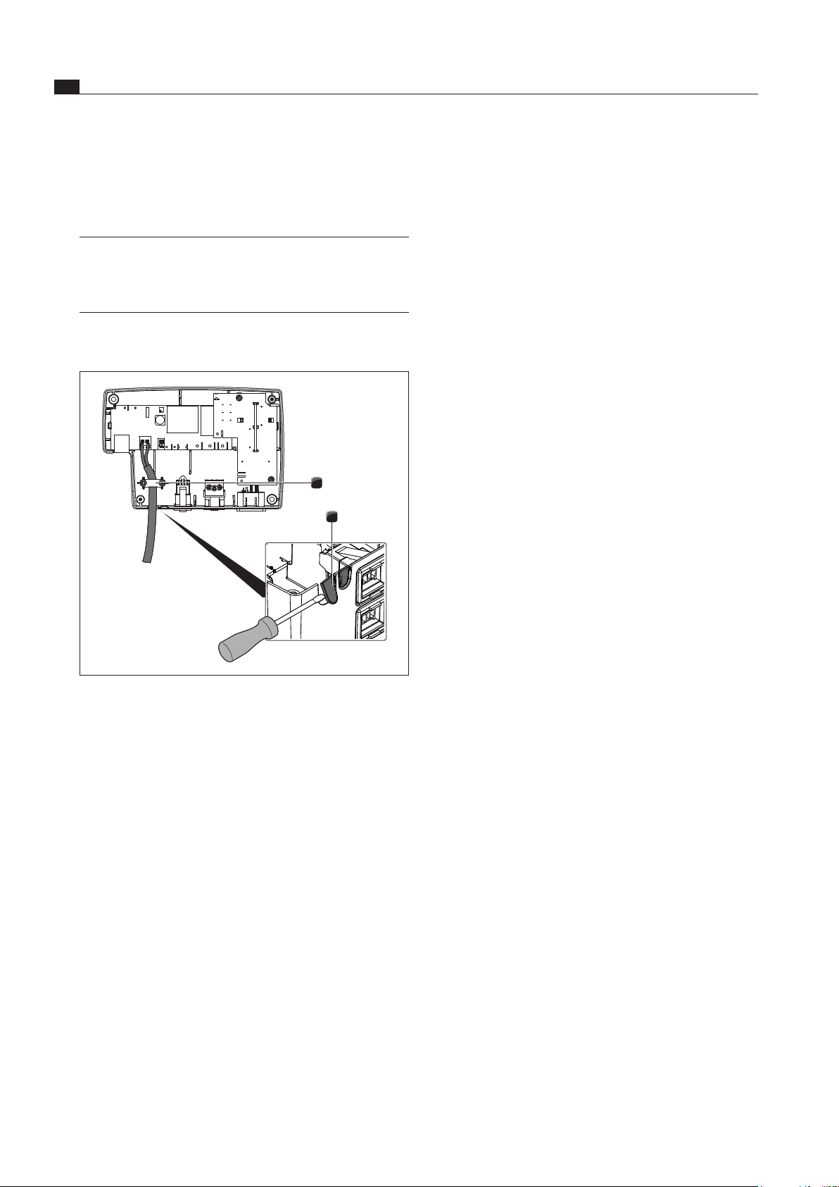
Fig. 6.30 Wrap the connection cable around the ferrite sleeve
three times
Wrap the connection cable around the ferrite sleeve
three times to create the desired filter performance.
Ensure that the cable end protrudes at least 120 mm
from the sleeve.
Prepare the connection cable in accordance with the
prescribed stripping lengths.
EN
24
Installation
For connections to the Home In connection clamp, no
ferrules may be used.
Clamp the connection cable in the strain relief clamp
[4] in accordance with the wire cross section used.
INFO If external switching devices are connected
both to the Home In and Home Out interfaces,
both cables should be secured with the strain
relief clamp [4].
Remove the relevant snap-out element [2] in the
plastic housing of the control unit.
1
2
Fig. 6.33 Home Out contacts with strain relief
[1] Strain relief clamp
[2] Snap-out element for cable feed
Check that the connection cables have been correctly
installed and securely connected.
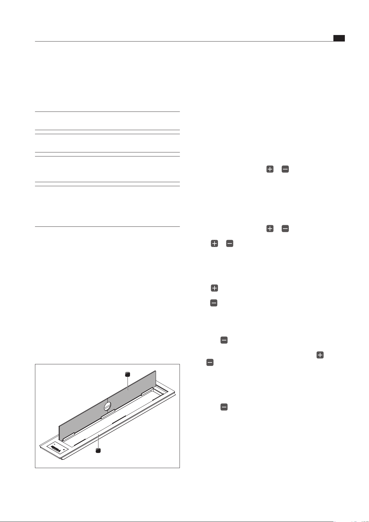
Close the cover on the control unit.
Make sure that the cable is not damaged.
Switch on the main switch/automatic circuit breaker.
Establishing the power connection
Connect the power supply cable for the control unit to
the power supply.
Put the cooktop extractor into operation (see the
Operation section).
Check that all the functions are working correctly.
6.8 Handover to user
Once installation is complete:
Explain the main functions to the user.
Explain all safety-related aspects of operation and
handling to the user.
Provide the user with the accessories and operating
and installation instructions for safe storage.
www.bora.com
EN
25
Operation
www.bora.com
7 Operation
Observe all safety and warning information during
operation (see the Safety section).
INFO The cooktop extractor should only be operated
with BORA cooktops.
INFO Only switch on the cooktop extractor if one of
the two cover plates is open.
INFO The cooktop extractor should only be
operated when the stainless steel grease filter
is installed.
INFO When using two gas cooktops, we recommend
using two additional cover plates. You can
obtain these from your specialist supplier or by
contacting BORA via the website
www.bora.com.
7.1 Operating the cooktop extractor
Recommendations for efficient vapour extraction
Always use a lid on pots, particularly those that are
high. This ensures effective vapour extraction. It also
reduces power consumption.
Only operate the cooktop extractor at the minimum
power level required for effective vapour extraction.
This makes it possible to improve the performance of
the odour filters in recirculation mode.
Only operate the hob at the minimum power level
required for cooking. This reduces cooking vapours
and power consumption.
Avoid strong drafts.
7.1.1 Opening the cover plates
1
2
Fig. 7.1 Using the cover plates
[1] Cover plates
[2] Cooktop extractor frame
Remove the cover plates [1] from the cooktop
extractor frame [2].
Store the cover plates in the side guide groove on the
cooktop extractor frame.
When using multiple hobs, remove the cover plates
from the cooktop extractor frame.
When using a gas cooktop, use the cover plates as an
air baffle to prevent any burner flame delay.
For this purpose, insert the cover plates into the side
guide groove on the side of the cooktop extractor
frame facing the gas cooktop.
Switching on
Use your finger to press the or button for
approx. 2 seconds to switch on the cooktop extractor.
0
is shown in the fan display. In case of no further input,
the cooktop extractor will switch off automatically after
about 10 seconds.
Switching off
Use your finger to press the or button to switch
off the cooktop extractor.
Press or several times until the fan indicator
0
is
displayed.
If the fan indicator displays
0
, the cooktop extractor is
switched off automatically after 5 seconds.
7.1.2 Adjusting the power level
Press to increase the power level from level 1 to
level 5.
Press to reduce the power level from level 5 to level 0.
7.1.3 Automatic after-run
Activation
Press the button until the power level
n
is
displayed for automatic after-run.
While the device is on, simultaneously press the
and buttons until the automatic after-run
n
is
displayed.
The cooktop extractor switches off automatically after
20 minutes.
Early deactivation
Press the button until the fan indicator
0
is
displayed.
EN
26
Operation
www.bora.com
7.2 Pay attention to the filter service
display
If
F
appears on the fan display, this means the service
life of the activated charcoal filter has expired (with
recirculation only) and the stainless steel grease filter
needs to be thoroughly cleaned.
Press the or button to set the desired power
level and switch to the normal operating mode.
Changing the filter
Switch off the cooktop extractor.
Observe all the information provided in the Cleaning
section.
Replace the activated charcoal filter.
Clean the stainless steel grease filter.
Resetting the filter service display
If the activated charcoal filter has been replaced and the
stainless steel grease filter has been cleaned, it will be
necessary to reset the filter service display.
Switch off the cooktop extractor.
F
is displayed in the fan indicator.
Simultaneously press and for at least 5 seconds
until a
0
is permanently displayed in the fan indicator.
The filter service display has been reset.
The filter service display can only be reset if a filter
service is due after 200 operating hours.
7.2.1 Closing the cover plates
After switching off the cooktop extractor, close it with
the two cover plates.
EN
27
Cleaning and Maintenance
www.bora.com
8 Cleaning and
Maintenance
Observe all safety and warning information
(see the Safety section).
INFO Clean the stainless steel surfaces in the
polishing direction only.
Regular cleaning and maintenance ensures the
longevity of the product and optimal function.
Adhere to the following cleaning and maintenance
cycles:
Component Cleaning cycle
Cooktop extractor
interior and surface
After cooking very greasy dishes;
at least once a week
Cover plates and
stainless steel grease filter
After cooking very greasy dishes;
at least once a week
Activated charcoal
filter (with recirculation
only)
Replace if odours have built up
or the service life has expired
(see the operating instructions
for the activated charcoal filter)
Tab. 8.1 Cleaning cycles
8.1 Cleaning agents
INFO Due to the use of aggressive cleaning agents
and abrasion caused by the pot bases the
surface will become damaged and dark stains
will occur.
Never use steam cleaners, abrasive sponges, scouring
pads or chemically aggressive cleaning agents
(e.g. oven cleaner spray).
Make sure that the cleaning agent does not contain
any sand, soda, acids, lyes or chloride.
8.2 Cleaning the cooktop extractor
Grease particles and limescale residues from cooking
vapours can settle on the surface and in the extraction
system.
Make sure that the cooktop extractor is switched off
(see the Operation section).
Remove the cover plates and stainless steel grease
filter prior to cleaning.
Clean the cooktop extractor in accordance with the
cleaning cycles.
Clean the surfaces using a soft, damp cloth,
detergent or a mild window cleaning agent.
Soften dried on dirt using a damp cloth
(do not scrape it off!).
8.2.1 Removing the cover plates and the
stainless steel grease filter
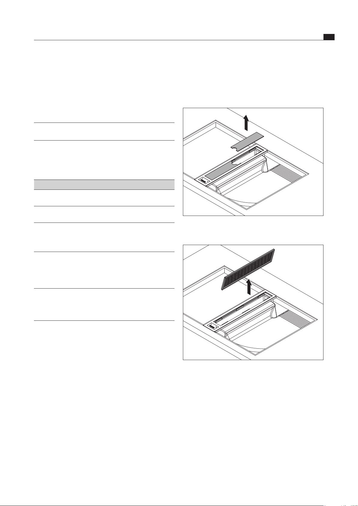
Fig. 8.1 Removing the cover plates
Lift the cover plates off upwards.
Fig. 8.2 Removing the stainless steel grease lter
Reach into the opening in the cooktop extractor and
remove the stainless steel grease filter.
8.2.2 Cleaning the cover plates and the
stainless steel grease filter
The cover plates and stainless steel grease filter can
be cleaned manually or in the dishwasher.
Manual cleaning
Use a detergent with a degreasing agent.
Rinse the cover plates and stainless steel grease filter
with hot water.
Clean the cover plates and stainless steel grease filter
with a soft brush.
Rinse the components thoroughly after cleaning.
EN
28
Cleaning and Maintenance
www.bora.com
8.3 Replacing the activated
charcoal filter
In recirculation mode, an additional activated charcoal
filter is used. The activated charcoal filter absorbs cooking
odours. The activated charcoal filter is installed on the
plinth fan or the duct system.
INFO Regularly replace the activated charcoal filter.
The service life can be found in the operating
instructions for the relevant activated charcoal
filter.
INFO You can obtain activated charcoal filters from
your specialist supplier or by contacting BORA
via the website at www.bora.com.
A description of how to replace the activated charcoal
filter can be found in its operating instructions.
Reset the filter service display
(see the Device description section).
Cleaning in the dishwasher
Rinse the cover plates and stainless steel grease filter
with a rinsing program at maximum 65 °C.
The stainless steel grease filter absorbs the greasy
particles from cooking vapours.
If it is no longer possible to clean the stainless steel
grease filter completely, it must be replaced.
8.2.3 Installing the cover plates and
stainless steel grease filter
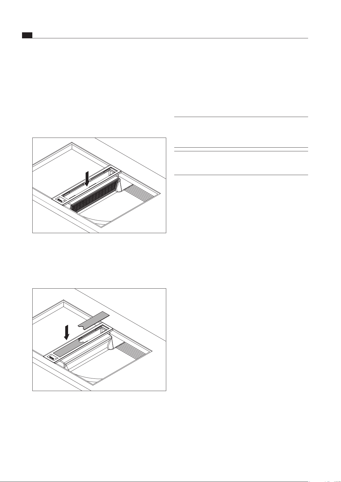
Fig. 8.3 Inserting the stainless steel grease lter
Insert the stainless steel grease filter into the opening
in the cooktop extractor.
Ensure that the stainless steel grease filter is
positioned in the gap in the cooktop extractor
housing; it does not need to be locked into place.
Fig. 8.4 Inserting the cover plates
Insert the cover plates.

EN
29
Troubleshooting
www.bora.com
9 Troubleshooting
Observe all safety and warning information (see the Safety section).
Operating situation Cause Remedy
The cooktop extractor cannot be
switched on.
The fuse or automatic circuit breaker of the
electrical wiring system in the apartment
and/or house is defective.
Replace the fuse.
Switch the automatic circuit breaker back
on.
The fuse or the automatic circuit
breaker trips several times.
Call the BORA Service Team.
The power supply is disconnected. Have a specialist electrician inspect the
power supply.
The microfuse in the universal control unit‘s
cooling device plug is defective.
Replace the fuse
(type: T3, 15 A/250 V).
E
flashes in the fan display for 5 seconds
and the fan is switched off.
The Home-In contact is broken. When using a window contact switch
(safety device), the window must be open
when the fan is operating.
The safety device is defective. Call the BORA Service Team.
Odours form when operating the cooktop
extractor.
This is normal on brand-new
appliances.
Odours stop forming after a few
operating hours.
The extraction performance of the cooktop
extractor has decreased.
The stainless steel grease filter is
heavily soiled.
Clean or replace the stainless steel grease
filter.
The activated charcoal filter is heavily soiled
(recirculation only).
Replace the activated charcoal filter.
There is an object in the air guiding housing
(e.g. cleaning cloth).
Remove the object.
The fan is defective or a duct
connection has become loose.
Call the BORA Service Team.
Tab. 9.1 Resolving a fault
In all other instances, call the BORA Service Team (see the Warranty, service and spare parts chapter).
EN
30
Decommissioning, disassembly and disposal
www.bora.com
10 Decommissioning,
disassembly and
disposal
Observe all safety and warning information
(see the Safety section).
Follow the enclosed manufacturer’s information.
10.1 Decommissioning
Decommissioning is understood as final shutdown and
disassembly. Following decommissioning, the device can
either be installed into other units, sold on privately or
disposed of.
INFO Electricity and gas connections may only be
disconnected by qualified specialists.
To decommission, switch the device off
(see Operation section)
Disconnect the device from the power supply.
10.2 Disassembly
For removal, the device must be accessible for
disassembly and disconnected from the power supply.
For gas devices, make sure the gas connection is
disconnected.
Undo the mounting brackets.
Remove the silicone joints.
Disconnect the device from the extractor duct.
Remove the device from the worktop by lifting it
upwards.
Remove any other accessories.
Dispose of the old device and any contaminated
accessories as described under “ Environmentally-
friendly disposal”.
10.3 Environmentally-friendly disposal
Disposal of transport packaging
INFO The packaging protects the device from
damage in transport. The packaging materials
have been selected from environmental and
disposal perspectives and are therefore
recyclable.
Returning the packaging to the materials cycle saves
resources and reduces waste volumes. Your specialist
supplier will take the packaging back.
Give the packaging to your specialist supplier
or
Dispose of the packaging properly in line with local
regulations.
Disposal of old appliance
Electrical devices marked with this label
may not be disposed of in domestic
waste at the end of their service
life. They must be disposed of at a
collection point for the recycling of old
electrical or electronic devices. You
can find information from your city or
district council.
Many electrical and electronic devices still contain
valuable materials. But they also contain damaging
materials which were necessary for them to function
properly and safely. These can damage human health or
the environment if disposed of improperly or incorrectly
handled.
Never put your old appliance in domestic waste.
Take the old appliance to a regional collection point
for return and recycling electrical and electronic
components and other materials.
EN
31
Warranty, technical service, spare parts, accessories
www.bora.com
11 Warranty, technical
service, spare parts,
accessories
Observe all safety and warning information
(see the Safety section).
11.1 Warranty
The warranty period is 2 years.
If you register at www.mybora.com/registration, the
warranty period is extended to 3 years.
11.2 Service
BORA Service:
see back page of operation and installation instructions
+800 7890 0987
If there are faults which you are not able to resolve
yourself, please contact your BORA specialist supplier
or the BORA Service Team.
The BORA Service Team requires the type designation
and the build number of your appliance (FD number). Both
pieces of information can be found on the nameplate on
the back of the instructions and on the appliance base.
11.3 Replacement parts
Only use original spare parts for repairs.
Repairs may only be carried out by the BORA Service
Team.
INFO Replacement parts can be obtained from your
BORA dealer, the BORA online service website
at www.bora.com/service or by calling the
service number provided.
11.4 Accessories
CKAAB0 cover plate
CKAEG air inlet grille
UEF stainless steel grease filter
UFH ferrite sleeve set
Type I UNLI (AUS) power supply
Type J UNLJ (CH) power supply
Type G UNLG (GB-IE) power supply

Germany:
BORA Lüftungstechnik GmbH
Rosenheimer Str. 33
83064 Raubling
Germany
T +49 (0) 8035 / 9840-0
F +49 (0) 8035 / 9840-300
www.bora.com
Austria:
BORA Vertriebs GmbH & Co KG
Innstraße 1
6342 Niederndorf
Austria
T +43 (0) 5373 / 62250-0
F +43 (0) 5373 / 62250-90
www.bora.com
Europe:
BORA Holding GmbH
Innstraße 1
6342 Niederndorf
Austria
T +43 (0) 5373 / 62250-0
F +43 (0) 5373 / 62250-90
www.bora.com
Australia - New Zealand:
BORA APAC Pty Ltd
100 Victoria Road
Drummoyne NSW 2047
Australia
T +61 2 9719 2350
F +61 2 8076 3514
www.bora-australia.com.au
Nameplate:
(please affix)
+800 7890 0987