Loading ...
Loading ...
Loading ...
13 ŶEnglish
Indoor Unit Installation
%QPPGEVKQPQHYKTKPIDGVYGGPWPKVUITQWPFYKTGCPFTGOQVGEQPVTQNNGTYKTKPI
9KTKPIDGVYGGPWPKVUCPFITQWPFYKTG
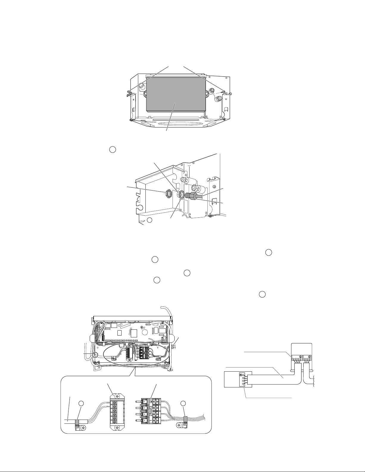
1) Remove the electrical wiring box cover (2 screws).
Screws
Electrical wiring box cover
2) Insert the wires including the ground wire into the conduit, and secure the conduit to the hole in the electrical wiring box
using a lock nut and the
N
washer for conduit, as shown in the illustration.
Lock nut
ƂGNFUWRRN[
%QPFWKV
ƂGNFUWRRN[
*QNGKPVJGGNGEVTKECN
YKTKPIDQZ
9CUJGTHQTEQPFWKV
N
%QPFWKVRKRG
3) Connect the ground wire to the corresponding terminals.
4) /CVEJYKTGEQNQTUYKVJVGTOKPCNPWODGTUQPVJGVGTOKPCNDNQEMHQTRQYGTUWRRN[QHKPFQQTCPFQWVFQQTWPKVCPFƂTON[
secure the wires in the corresponding terminals with screws.
5) +PFQKPIVJKURWNNVJGYKTGUKPUKFGVJTQWIJVJGJQNGCPFƂZVJGYKTGUUGEWTGN[YKVJVJGKPENWFGF
D
clamp.
6)
Give enough slack to the wires between the
D
clamp and terminal block for power supply.
7) Pull the wires inside through the hole and connect them to the terminal block for remote controller (no polarity).
5GEWTGN[ƂZVJGTGOQVGEQPVTQNNGTYKTKPIYKVJVJGKPENWFGF
D
clamp.
8) Give enough slack to the wires between the
D
clamp and the terminal block for remote controller.
9) Attach the electrical wiring box cover as before.
10) #HVGTCNNYKTKPIEQPPGEVKQPUCTGFQPGƂNNKPCP[ICRUKPVJGECUKPIYKTKPIJQNGUYKVJRWVV[QT
M
sealing pad (small) thus
to prevent small animals or dirt from entering the unit from outside and causing short circuits in the electrical wiring box.
Terminal block for remote controller
Clamp
D
Terminal block for power supply
Clamp
D
Opening for cable
Remote controller wiring
Conduit
123
123
L1 L
2
(KTON[ƂZVJGYKTGUYKVJ
VJGVGTOKPCNUETGYU
1WVFQQT
WPKV
+PFQQT
WPKV
(KTON[ƂZVJGYKTGUYKVJ
VJGVGTOKPCNUETGYU
9KTGUK\GCPFNGPIVJOWUV
EQORN[YKVJNQECNEQFGU
Loading ...
Loading ...
Loading ...