Loading ...
Loading ...
Loading ...
Adjustments for Wear
Bevel Lock
The purpose of the bevel lock is to lock the
motor at any bevel angle. An adjustment is
required if the motor can be easily moved by
hand when the bevel lock is locked or if bevel
lock offers minimal resistance when moving it
to the locked position. To make this adjust-
ment:
L Remove motor" support cover.
2oPosition the motor at approximately 30°
bevel angle and lock bevel lock_ (Figure 143)
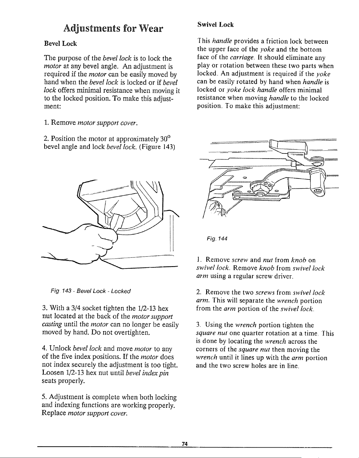
Swivel Lock
Ihis handle provides a fr'iction lock between
the upper face of the yoke and the bottom
t'ace of the carriage. It should eliminate any
play or' rotation between these two parts when
locked. An adjustment is required if the yoke
can be easily rotated by hand when handle is
locked or' ,yoke lock handle offers minimal
resistance when moving handle to the locked
position° To make this adjustment:
Fig. 144
Fig !43 * Bevel Lock - Locked
3. With a 3/4 socket tighten the 1/2-13 hex
nut located at the back of the motorsupport
casting until the motor can no longer be easily
moved by hand. Do not overtighten.
4, Unlock bevel lock and move motor to any
of the five index positions. If the motor does
not index securely the adjustment is too tight.
Loosen 1/2-13 hex nut until bevel indexpin
seats properly.
5oAdjustment is complete when both locking
and indexing functions are working properly.
Replace motor support cover:
1_ Remove screw and nut trom knob on
swivel lock_ Remove knob from swivel lock
arm using a regular screw driver.
2. Remove the two screws from swivel lock
arm. This will separate the wrench portion
from the arm portion of' the swivel lock
3_ Using the wrench portion tighten the
square nut one quarter rotation at a time,, Ihis
is done by locating the wrench across the
corners ot the square nut then moving the
wrench unti! it lines up with the arm portion
and the two screw holes are in line,,
74
Loading ...
Loading ...
Loading ...