
Loading ...
Loading ...
Loading ...
ATTACHING AND ASSEMBLING TABLE i:XTENS ONS
If you received Table Extensions with_ou,r Saw attach
them at this time.
1. From among the loose parts find the following
hardware.
4 Corner Support Brackets
4 Corner Stiffener Brackets
16 Truss Hd. Screws 1/4-20 x 1
16 Ext. Lockwashers 1/4
16 Hex Nut I/4-20
8 Hex Hd. Screws 5/16-18x 1-1/4
8 Ext. Lockwasher 5/16
8 Hex Nut5/16-18
4 Flat Washers (Dia. of hole 17/64)
8 Flat Washers (Dia. of hole 11/32)
Assemble brackets with hardware as listed.
Insert 5/16-18 x 1-1/4 in. long screws through holes in
EXTENSION then through table. Install flat washer,
Iockwashers, and screw on the nuts . . . DO NOT
TIGHTEN.
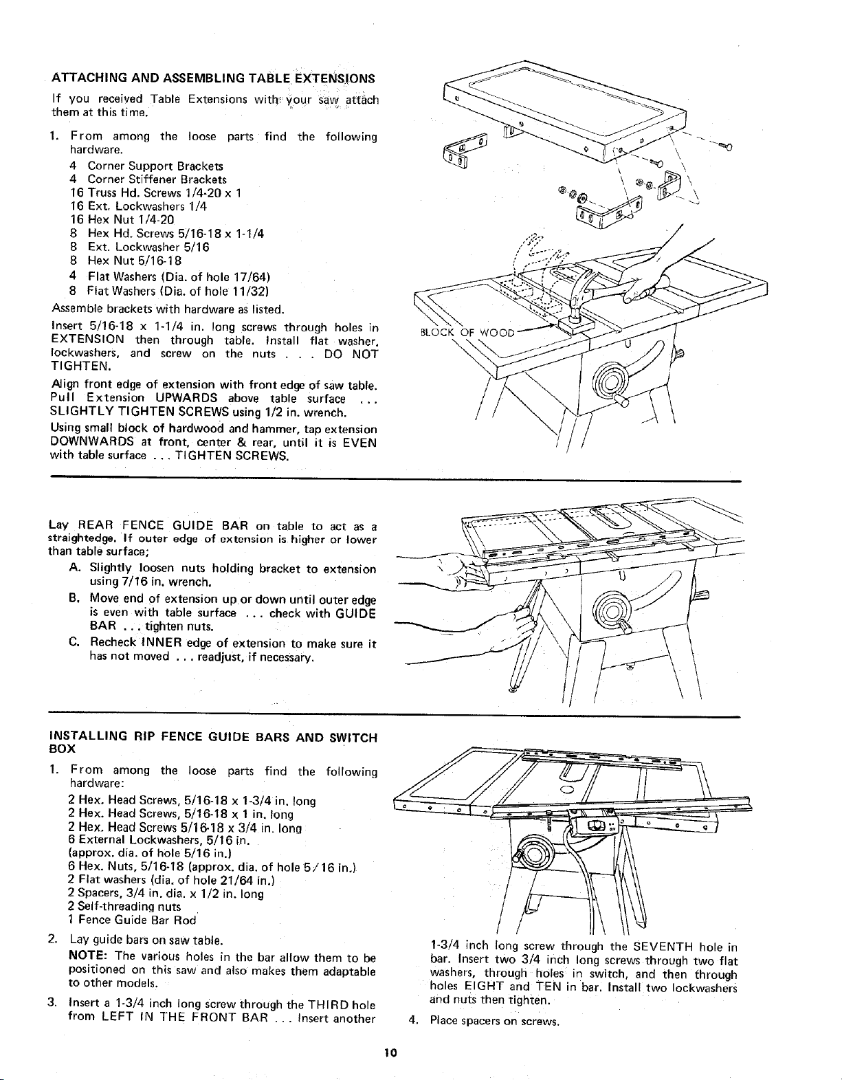
Align front edge of extension with front edge of saw table.
Pull Extension UPWARDS above table surface ...
SLIGHTLY TIGHTEN SCREWS using 1/2 in. wrench.
Using small block of hardwood and hammer, tap extension
DOWNWARDS at front, center & rear, until it is EVEN
with table surface ... TIGHTEN SCREWS.
BLOCK OF WOOC
\
Lay REAR FENCE GUIDE BAR on table to act as a
straightedge. If outer edge of extension is higher or lower
than table surface;
A. Slightly loosen nuts holding bracket to extension
using 7/16 in. wrench.
B. Move end of extension u _ or down until outer edge
is even with table surface ... check with GUIDE
BAR ... tighten nuts.
C. Recheck INNER edge of extension to make sure it
has not moved ... readjust, if necessary.
\ \
INSTALLING RIP FENCE GUIDE BARS AND SWITCH
BOX
From among the loose parts find the following
hardware:
2 Hex. Head Screws, 5/16-18 x 1-3/4 in. long
2 Hex. Head Screws, 5/16-18 x 1 in. long
2 Hex. Head Screws 5/1&18 x 3/4 in. Ion_
6 External Lockwashers, 5/16 in.
(approx. dia. of hole 5/16 in.)
6 Hex. Nuts, 5/16-18 (approx. dia. of hole 5/16 in.)
2 Flat washers (dia. of hole 21/64 in.)
2 Spacers, 3/4 in. dia. x 1/2 in. long
2 Self-threading nuts
1 Fence Guide Bar Rod
Lay guide bars on saw table.
NOTE: The various holes in the bar allow them to be
positioned on this saw and also makes them adaptable
to other models.
3. Insert a 1-3/4 inch tong screw through the THIRD hole
from LEFT IN THE FRONT BAR ... Insert another
/
/
1-3/4 inch long screw through the SEVENTH hole in
bar. Insert two 3/4 inch long screws through two flat
washers, through holes in switch, and then through
holes EIGHT and TEN in bar. Instal two Iockwashers
and nuts then tighten.
4. Place spacers on screws.
10
Loading ...
Loading ...
Loading ...