Loading ...
Loading ...
Loading ...
24
INSTALLATION OVERVIEW
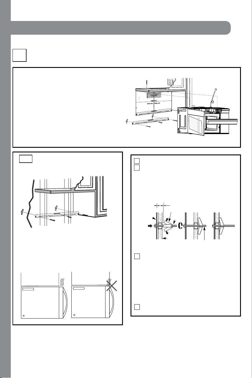
C1. Attach Mounting Plate to Wall
C2. Pr epar e Top Cabi net
C4.
C5.
Mount t h e Microwave Oven
I MPORTAN T N OT ES:
• M ake sur e the scr ews f or t h e blower mot or and bl ower
pl ate ar e secur ely tightened when th ey are r ein st al led.
This will help to prevent excessive vibration.
• M ake sur e the motor wir ing has been pr oper l y routed
and secured, and that the wires are not pinched.
Inst allat ion Inst ruct ions
Pl ace th e moun ti n g p l at e agai n st t h e wal l an d
insert the toggle wings into the holes in the wall
to mount the plate.
NO T E: Before tightening toggle bolts and wood
screw, make sure the bott m of the mounting plate
touch the bottom of the cabinet when pushed flush
agai n st t h e wal l an d th at t he pl ate i s pr oper l y
cent er ed un der the cabi net .
CAUTION: Be careful to avoid pinching fingers
between the back of th e moun t ing pl ate and the wal l .
Tighten all bolts. Pull the plate away from the wall
to help tighten the bolts.
4
3
ATTACH THE M OUNTING
PLATE TO THE WALL
C1.
Attach the plate to the wall using toggle bolts.
At least one wood screw must be used to attach
the plate to a wall stud.
Remove th e t oggle wings f r om th e bol t s.
Insert the bolts into the mounting plate through
the holes designated to go into drywall and
reattach the toggle wings to
3
⁄4″ (19 mm) onto
each bolt.
1
Wal l
Mounti ng
Plate
Spaci ng for Toggl es
More Than Wal l
Thi ckness
Bol t End
Toggle
Bol t
Toggle Wi ngs
To use toggle bolts:
2
RECIRCULATING (Non-Vent ed Ductless)
C
Install or change Charcoal Filter
C3. Check Bl ower Plate
NO T E:
Cabi net
Cabi net
If the cabinet depth including the cabinet doors
is more than 13""'' then the unit must be spaced
out from wall using adequate materials supporting
150 Ibs to allow proper top vent air exhaust/ intake.
o
EN-20
12
"
4"
NO
T
E
:ITI
S VER
Y I
MP
ORTANT
T
O
R
EAD AN
D F
O
LLO
W
T
H
E DIRECTIONS
I
N
T
H
E
INST
ALL
ATIO
N
I
NSTR
UCTION
S
BE
F
ORE PR
O
C
EE
D
I
NGW
IT
H
T
HIS
REAR W
ALL TEM
PL
AT
E
.
This
R
e
ar
Wa
ll
Temp
la
te serves to
positionthe b
ottom
mo
unti
n
g pl
a
tea
n
d
to
loca
t
eth
e
h
or
izo
nt
al exh
aust
ou
tle
t
.
1
.Usea lev
eltocheck th
a
t
t
h
e
te
mp
late
i
sp
ositi
o
ne
d
a
ccuratel
y.
2. L
o
ca
te a
n
d
ma
rk at
l
east o
ne
stu
d
o
n
th
e lef
t
o
r
r
igh
t si
d
e o
f
thec
en
te
rline.
It
isimporta
nt
to
u
s
e
a
t le
a
sto
n
e wood
screw
mou
nte
d
fi
rm
ly
in a
s
tu
d
tosu
p
p
o
rt
t
he
weigh
t
of themicrowave.Mark two
addi
tio
nal,even
lyspace
d
locationsfor the su
ppliedt
ogg
le
b
ol
ts.
3
. Drill holes
inth
e m
arked lo
ca
tio
ns
.Wh
e
re the
r
eis
a s
tud
,d
rilla
3/16
"
ho
le
f
or
wo
o
d
sc
r
e
ws. F
or
ho
les
th
a
t
do
n
ot
lin
e u
p
with a
stud
, drill5
/8
"
h
o
le
s
f
o
r
to
g
g
le bolt
s.
DO
N
OT
I
N
S
TALL TH
E
MOU
NTINGP
LA
TE
A
T
THIS
TIM
E.
4
. Re
m
ove
th
e te
mp
lat
e fro
m t
he
rea
r
wa
l
l.
5. Reviewthe
I
n
sta
lla
ti
on
In
stru
cti
onb
o
o
k f
or
you
r
in
st
allation
si
tu
a
tio
n
.
Loc
a
t
ean
d
ma
rk holes to
a
lign with holes in the
mount
i
ng pl
ate.
I
MPORT
ANT:
LOCA
T
E AT
LEAST ONESTUD
O
N
EI
T
H
ER SIDE
OF
T
H
E
CE
N
TE
R
L
I
NE.
MARK T
HEL
O
CA
T
IO
N F
O
R2 ADDITION
AL, EVENLY
SPACED TO
G
GLE BOLT
S
IN TH
E
MO
U
N
TING
PLATE
AREA
.
Loc
at
e
a
nd
mark hole
s
t
o
al
i
gn
wi
t
h hol
es
int
h
e
m
o
un
tin
g
p
lat
e.
I
MPO
RTA
NT
:
LO
C
AT
E
AT LEAST
O
NEST
UD
ON EITHER SIDE
O
F
THECENT
E
RLINE.
MARK T
H
E
LOCA
TION F
OR
2 AD
DIT
ION
AL
,
EVENLY
SPACED TOG
G
LE
BO
L
T
SIN
T
H
E
MOUNT
IN
GPLATE
AREA.
T
r
im the rear wa
ll te
m
plate
alon
g
th
e
d
o
tted
li
n
e.
Dar
le
v
uel
taala ho
ja
par
aconsul
t
ar
la
v
e
r
s
ió
ne
n
Es
p
año
l.
3/8"TO
EDG
E
Trim t
he
rear wall t
em
pla
t
e along
t
h
e dotted lin
e.
INSTALLATION
Loading ...
Loading ...
Loading ...