Loading ...
Loading ...
Loading ...
19
INSTALLATION OVERVIEW
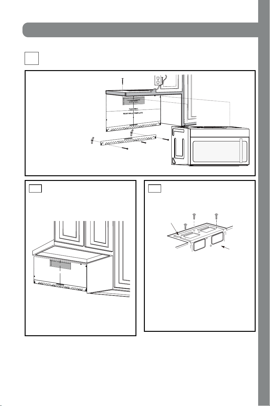
B1. Pr epar e Rear Wal l
B3. Attach Mounting Plate to Wall
B4. Pr epare Top Cabi n et
B5. Adjust Blower
B6. Moun t t h e Mi cr owave Oven
I MPORTAN T NOT ES:
• M ake sur e th e scr ews for th e
blower motor and blower plate
are secur el y ti ghtened when
they are reinstalled. This will
help to pr event excessi ve
vibration.
•
been properly routed and secured,
and that the wires are not pinched.
Remove and save the screw th at hol ds the bl ower
plate to the microwave. Lift off the blower plate.
Back of
Microwave
Installation Instruct ions
PREPARING THE REAR WALL
FOR OUTSIDE BACK EXHAUST
B1.
You need to cut an opening in the rear wall for
outside exhaust.
• Read the instructions on the REAR
WALL TEMPLATE.
• Tape i t t o t he r ear wal l .
• Cut the opening, following the instructions of the
REAR WALL T EM PLATE.
B2.
OUTSIDE BACK EXHAUST (Horizont al Duct )
B
Blower Pl at e
REM OVE BLOWER PLATE
B2. Remove Bl ower Pl ate
3/8" TO EDGE
NOTE: IT IS VE
RY IMPORTANT TO
READ AND FOLLOW THE DIRECTIONS
IN THE INSTALLATION INSTRUCTIONS
BEFORE PROCEEDING WITH THIS
REAR WALL TEMPLATE.
This Rear Wall Template serves to position the bottom
mounting plate and to locate the horizontal exhaust
outlet.
1. Use a level to check that the template is positioned
accurately.
2. Locate and mark at least one stud on the left or
right side of the centerline.
It is important to use at least one wood
screw mounted firmly in a stud to support the weight
of the microwave. Mark two additional, evenly spaced
locations for the supplied toggle bolts.
3. Drill holes in the marked locations. Where there is
a stud, drill a 3/16" hole for wood screws. For holes
that do not line up with a stud, drill 5/8" holes for
toggle bolts.
DO NOT INSTALL THE MOUNTING PLATE
AT THIS TIME.
4. Remove the template from the rear wall.
5. Review the Installation Instruction book for your
installation situation.
Locate and mark holes to align with holes in the
mounting plate.
IMPORTANT:
LOCATE
AT LEAST ONE STUD ON
EITHER SIDE OF
THE CENTERLINE.
MARK THE LOCATION FOR
2 ADDITIONAL, EVENLY
SPACED TOGGLE BOLTS IN THE MOUNTING PLATE
AREA.
Locate and mark holes to align with holes in the
mounting plate.
IMPORTA
NT:
LOCATE AT LEAST ONE STUD ON EITHER SIDE OF
THE CENTERLINE.
MARK THE LOCATION FOR 2 ADDITIONAL, EVENLY
SPACED TOGGLE BOLTS IN THE MOUNTING PLATE
AREA.
Trim the rear wall template along the dotted line.
Trim the rear wall template along the dotted line.
12"
4"
Darle vuelta a la hoja para consultar la
versión en Español.
Make sure t h e motor wir ing has
12"
4"
NO
TE
: IT IS VERY
I
MPOR
TANT TO
READ AND FO
LLOWTHE DIRECTIONS
IN THE INSTALLATION INSTRU
CTI
ONS
BE
FO
RE PR
O
CEEDINGWITH TH
IS
REAR W
ALL TEMPLATE.
Thi
s
R
ea
rWall Templ
ate ser
ves to p
osition th
e botto
m
mounting platea
nd
to loc
ate th
e hor
izon
ta
l e
xhau
st
ou
t
let.
1. Us
e a l
ev
el
to
chec
k th
at the t
emplate is pos
itioned
accu
r
ately.
2. L
oc
ate a
ndmar
k at lea
st o
nestud on the left or
right
side of the centerli
ne.
016'
It is importa
nt to use at leas
t
one wo
od
sc
rew
mounted firmly
i
n a s
tud
to supp
ort the weight
of
the mic
r
owa
ve. M
ar
k two ad
dition
al, even
ly
spa
ced
locatio
ns f
o
r
the
supplied to
g
gle bol
t
s.
3. Dri
ll
h
ole
s in th
e marked locatio
ns.
Wher
e t
h
er
e is
a s
tud, dr
il
l
a 3/1
6"
hole for
wood scr
ews. F
or
holes
thatdo
n
o
t lin
e upwith
a
stud, d
r
ill 5
/8" holes fo
r
togg
le bolts
.
016'
DO
NOT
INSTALL
T
HE MO
U
NTI
NG P
L
ATE
AT THISTIME.
4. Re
move th
e te
mplate fr
o
m
the rea
r
wall.
5.Review
the In
s
ta
ll
a
tionInst
r
uc
tion book
for y
ou
r
installa
tion situat
i
on
.
Locate and mark holes
to ali
gn with holes in t
he
mounting
plate.
IMP
O
RTANT
:
LOCATE
AT LEAST ONE STUD
ON EI
THERSIDE OF
THE CENTE
RLINE.
MARKT
HE LO
CATIONF
O
R 2 ADDITIONAL, EVENLY
SP
ACE
D T
OGGLE
BOLTS IN THE MOUN
TING
PLATE
AREA.
Trim the re
ar wall tem
plat
e along
the do
tted line.
Da
rle
vu
elt
a
a
la
ho
ja
pa
ra
co
ns
ul
tarla
ver
sión
en
Espa
ñol.
Locate and mark
holes to ali
gn with holes in t
he
mountingplate.
IMPORTANT:
LOC
A
TE AT LEAST ONESTUD ON EITHER SI
D
E OF
THE
CENT
E
R
LI
N
E
.
MARKTHE LO
CATION
FOR 2 ADDITIONA
L, EV
ENL
Y
SPACEDTOGGLE BOLTS IN THE MO
UNTING PLATE
AREA.
Trim the rear wall templat
e along
the dotted line.
3/8"TO
EDG
E
EN-16
INSTALLATION
Loading ...
Loading ...
Loading ...