Loading ...
Loading ...
Loading ...
15
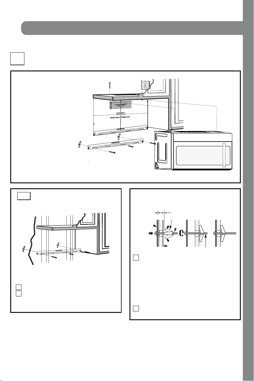
Pl ace th e moun ti n g p l at e agai n st t h e wal l an d
insert the toggle wings into the holes in the wall
to mount the plate.
NO T E: Before tightening toggle bolts and wood
scr ew, make sur e th e bottom of th e moun t ing pl ate
touch the bottom of the cabinet when pushed
flush against the wall and that the plate is properly
cent er ed un der the cabi net .
CAUTION: Be careful to avoid pinching fingers
between the back of th e moun t ing pl ate and the wal l .
Tighten all bolts. Pull the plate away from the wall
to help tighten the bolts.
3
4
ATTACH THE M OUNTING
PLATE TO THE WALL
A1.
Attach the plate to the wall using toggle bolts.
At least one wood screw must be used to attach
the plate to a wall stud.
Remove the t oggle wings f r om the bolt s.
Insert the bolts into the mounting plate
through the holes designated to go into drywall
and reattach the toggle wings to
3
⁄4″ ( 19 mm) onto
each bolt.
1
INSTALLATION OVERVIEW
A1. Attach Mounting Plate to Wall
A2. Prepare Top Cabi net
M ou n t Mi cr owave O ven
A5.
Adjust Exhaust Adaptor
A6.
Wal l
Mounti ng
Plate
Spaci ng for Toggl es
More Than Wal l
Thi ckness
Bol t End
Toggle
Bol t
Toggle Wi ngs
To use toggle bolts:
Inst allat ion Inst ruct ions
2
OUTSIDE TOP EXHAUST (Vert ical Duct )
A
I MPORTAN T N OT ES:
• M ake sur e the scr ews f or t h e
blower motor and blower plate
are secur ely tightened when
they are reinstalled. This will
hel p t o pr event excessi ve
vibration.
• M ake sur e the motor wir ing has
been properly routed and secured,
and that the wires are not pinched.
A7. Connect Ductwor k
A3.
A4.
Check Damper O per ati on
Adapting Microwave Blower for
Outside Top Exhaust
12"
4"
NO
TE
: IT IS VERY
I
MPOR
TANT TO
READ AND FO
LLOWTHE DIRECTIONS
IN THE INSTALLATION INSTRU
CTI
ONS
BE
FO
RE PR
O
CEEDINGWITH TH
IS
REAR W
ALL TEMPLATE.
Thi
s
R
ea
rWall Templ
ate ser
ves to p
osition th
e botto
m
mounting platea
nd
to loc
ate th
e hor
izon
ta
l e
xhau
st
ou
t
let.
1. Us
e a l
ev
el
to
chec
k th
at the t
emplate is pos
itioned
accu
r
ately.
2. L
oc
ate a
ndmar
k at lea
st o
nestud on the left or
right
side of the centerli
ne.
016'
It is importa
nt to use at leas
t
one wo
od
sc
rew
mounted firmly
i
n a s
tud
to supp
ort the weight
of
the mic
r
owa
ve. M
ar
k two ad
dition
al, even
ly
spa
ced
locatio
ns f
o
r
the
supplied to
g
gle bol
t
s.
3. Dri
ll
h
ole
s in th
e marked locatio
ns.
Wher
e t
h
er
e is
a s
tud, dr
il
l
a 3/1
6"
hole for
wood scr
ews. F
or
holes
thatdo
n
o
t lin
e upwith
a
stud, d
r
ill 5
/8" holes fo
r
togg
le bolts
.
016'
DO
NOT
INSTALL
T
HE MO
U
NTI
NG P
L
ATE
AT THISTIME.
4. Re
move th
e te
mplate fr
o
m
the rea
r
wall.
5.Review
the In
s
ta
ll
a
tionInst
r
uc
tion book
for y
ou
r
installa
tion situat
i
on
.
Locate and mark holes
to ali
gn with holes in t
he
mounting
plate.
IMP
O
RTANT
:
LOCATE
AT LEAST ONE STUD
ON EI
THERSIDE OF
THE CENTE
RLINE.
MARKT
HE LO
CATIONF
O
R 2 ADDITIONAL, EVENLY
SP
ACE
D T
OGGLE
BOLTS IN THE MOUN
TING
PLATE
AREA.
Trim the re
ar wall tem
plat
e along
the do
tted line.
Da
rle
vu
elt
a
a
la
ho
ja
pa
ra
co
ns
ul
tarla
ver
sión
en
Espa
ñol.
Locate and mark
holes to ali
gn with holes in t
he
mountingplate.
IMPORTANT:
LOC
A
TE AT LEAST ONESTUD ON EITHER SI
D
E OF
THE
CENT
E
R
LI
N
E
.
MARKTHE LO
CATION
FOR 2 ADDITIONA
L, EV
ENL
Y
SPACEDTOGGLE BO
LTS IN THE MO
UNTING PLATE
AREA.
Trim the rear wall templat
e along
the dotted line.
3/8"TO
EDG
E
EN-12
INSTALLATION
Loading ...
Loading ...
Loading ...