Loading ...
Loading ...
Loading ...
11
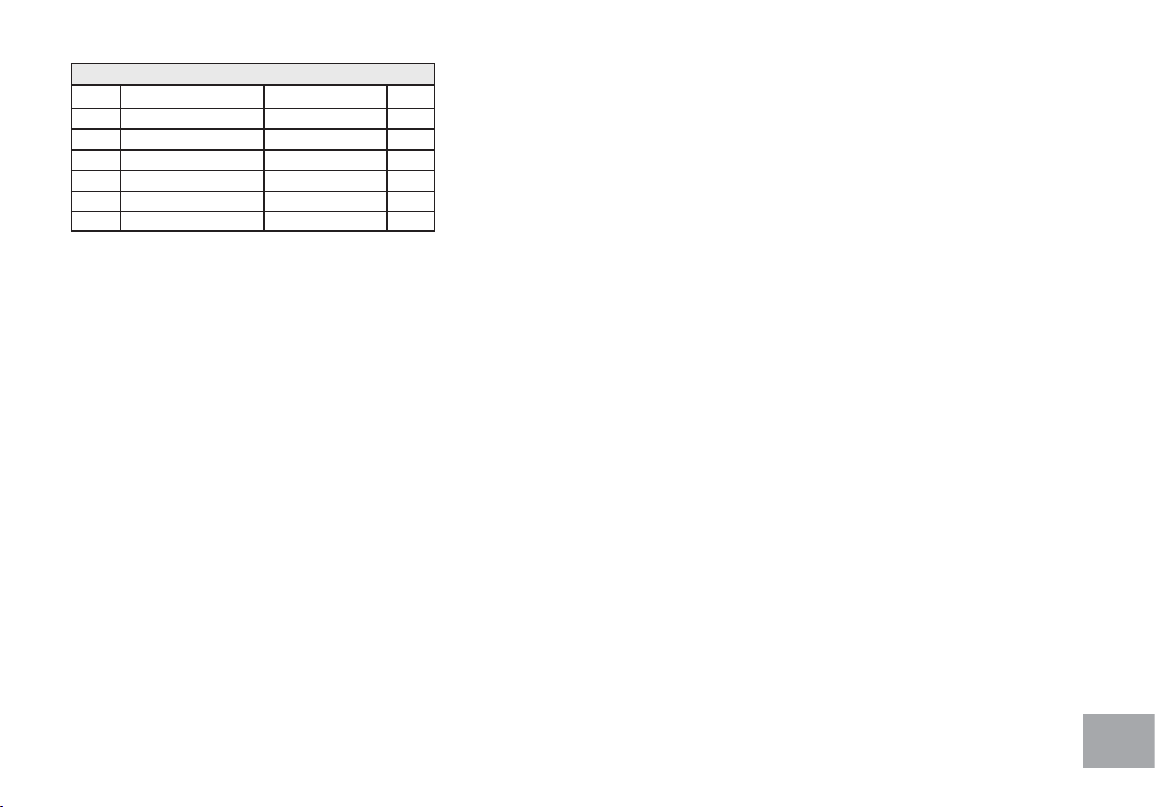
HARDWARE FOR STEP 1
PART TYPE DESCRIPTION QTY
106 BOLT
3/8” × 3-3/4”
2
144 WASHER
Ø10 × 2T
6
142 WASHER
3/8” x 23 x 2.0T
2
110 BOLT
3/8” × 3/4”
4
136 WASHER
Ø3/8” × Ø19 × 1.5T
4
113 SCREW
M5 × 10m/m
4
1. Gather HARDWARE FOR STEP 1.
2. Attach Rear Stabilizer with Handle (13) to mounting plate
on the main frame and secure with 2 Hex Head Bolts (106),
2 Split Washers (144) and Curved Washers (142) by using
13/14m/m Wrench (149).
3. Pull the tie on Computer Cable (2) to have Computer
Cable (46) go through the mast from bottom and out of the
mast on top. Secure the Console Mast on the mounting plate
on the Main Frame with 4 Socket Head Cap Bolts(110), 4
Split Washers (144) and 4 Flat Washers (136) by using L
Allen Wrench (152).
NOTE: DO NOT PINCH CABLE, AS THIS MAY CAUSE
MALFUNCTIONS.
4. Take off the tie from Computer Cable (46) and plug in onto
the Console Assembly (45) together with two Hand pulse
Assembly (51,52) and Resistance/ Incline (White/Red)
(61,62) cables.
5. Place the Console on the mounting plate of the Console
Mast and secure with 4 Phillips Head Screws (113) by using
Phillips Head Screw Driver (151)
Loading ...
Loading ...
Loading ...