
Loading ...
Loading ...
Loading ...
W415-2362 / A / 10.25.19
EN
42
operation
9.0 adjustments
9.1 pilot burner adjustment
9.2 fl ame characteristics
9.3 restricting vertical vents
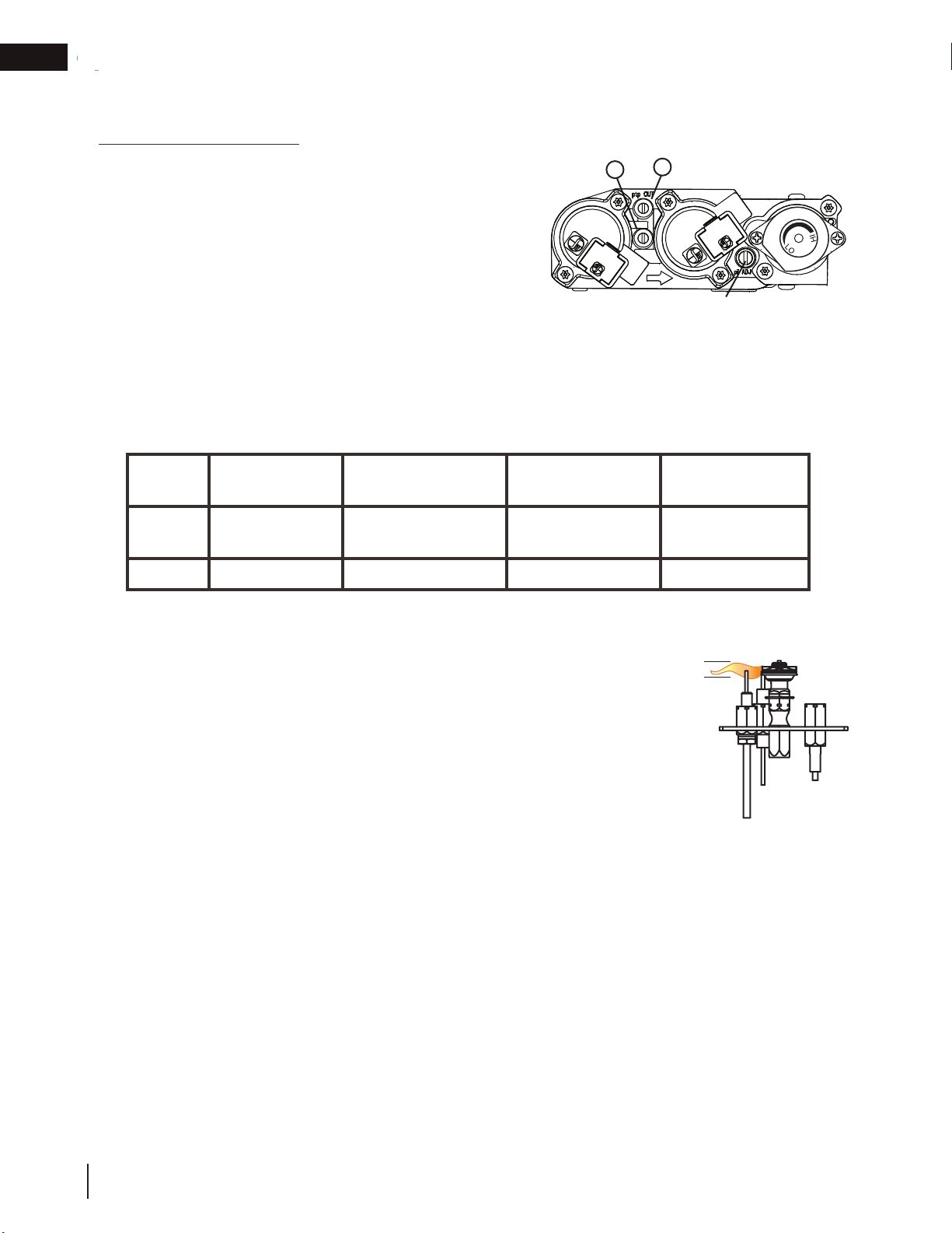
Adjust the pilot screw to provide properly sized fl ame. Turn in a clockwise direction to reduce the gas fl ow.
Check Pressure Readings:
Inlet pressure can be checked by turning screw (A) counter-
clockwise 2 or 3 turns and then placing pressure gauge tubing
over the test point. Gauge should read as described on the chart
below. Check pressure with main burner operating on “HI”.
Outlet pressure can be checked the same as above using screw
(B). Gauge should read as described on the chart below. Check
pressure with main burner operating on “HI”.
After taking pressure readings, be sure to turn screws
clockwise fi rmly to reseal. Do not overtorque.
Leak test with a soap and water solution.
Prior to pilot adjustment, ensure that the pilot assembly has not been painted. If overspray or painting of
the pilot assembly has occurred remove the paint from the pilot assembly, or replace. Fine emery cloth or a
synthetic scrub pad (such as Scotch-Brite
™)
can be used to remove the paint from the pilot hood, electrode
and fl ame sensor.
INSERT PILOT ASSEMBLY
*Maximum inlet
p
ressure not to exceed 13”
Pressure Natural Gas
(inches)
Natural Gas
(millibars)
Propane
(inches)
Propane
(millibars)
Inlet
*7”
(minimum 4.5”)
17.4mb
(minimum 11.2mb)
13”
(minimum 11”)
32.4mb
(minimum 27.4mb)
Outlet
3.5” 8.7mb 10” 24.9mb
It’s important to periodically perform a visual check of
the pilot and burner flames. Compare them to the
illustration provided. If any flames appear abnormal,
call a service person.
ADD IMAGE
HERE
Flame must envelop
upper
3/8" to 1/2"
(12.7mm - 9.5mm) of
Flame sensor
3/8” - 1/2”
(9.5mm - 12.7mm)
Vertical installations may display a very active fl ame. If this appearance is not desirable, the vent exit must be
restricted using a restrictor vent kit. Refer to the “replacement parts” section of the owner’s manual for the
appropriate kit. This will reduce the velocity of the exhaust gases, slowing down the fl ame pattern and creating a
more traditional
g
entle fl ame a
pp
earance. S
p
ecifi c instructions are included with the kit.
A
B
PILOT SCREW
Loading ...
Loading ...
Loading ...