Loading ...
Loading ...
Loading ...
Large Unit Heater
9
Operating Instructions and Owner’s Manual
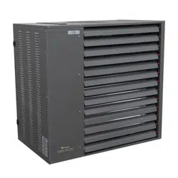
Venting Through Combustible Roof or Wall
FIGURE 6
Listed Thimble
Roof Flashing
Specified
Terminal
For vertical vent termination, the venting must comply with all the
General Venting Requirements and with the following vent locations
and clearances:
• Separate air intake duct from vent pipe by a minimum of 4 feet by
placing vent pipes higher than adjacent air intake ducts.
• Utilize a listed type B vent termination cap.
• The vent terminal must extend a minimum of 2 feet above the roof.
• Vent caps should be located a minimum of 2 feet away from
adjoining structures.
• All vertically vented heaters that are Category I must be connected
to a chimney or vent complying with a recognized Standard, or
lined masonry (or concrete) chimney with a material acceptable to
the authority having jurisdiction. Venting into an unlined masonry
chimney is not permitted. Refer to the National Fuel Gas Code.
• Use a listed vent terminal to reduce down drafts and moisture in the
vent.
• Ensure the vent connector runs as short as possible with a minimum
number of elbows. Refer to the (American) National Fuel Gas Code
ANSI Z223.1 or (Canada) CSA B149.1 Natural Gas and Propane
Installation Code for maximum vent and vent connector lengths.
Horizontal run of the vent connector from the induced draft blower
to the chimney/vent cannot exceed the values in Table 4.
• When the length of a single wall vent including elbows, exceeds 5
feet (1.5m), the vent shall be insulated along its entire length with a
minimum of 1/2” thick foil faced fiberglass 1-1/2# density insulation.
If a single wall vent is used in an unheated area it shall be insulated.
Failure to do so will result in condensation of flue gases.
• All vertical type B-1 vents, single wall vents, or listed chimney lining
system must be terminated with a listed vent cap or listed roof
assembly.
• The vent must extend at least 3’ (1m) above the highest point
where it passes through a roof of a building and at least 2’ (0.6m)
higher than any part of a building within a horizontal distance of
10’ (3.05m) unless otherwise specified by the (American) National
Fuel Gas Code, ANSI Z223.1 or (Canada) CAN/CGA-B149 Installation
Code. The vent must extend at least 5’ (1.6m) above the highest
connected equipment flue collar.
HORIZONTAL VENTING
An appliance that operates with a positive vent static pressure
and with a vent gas temperature that avoids excessive condensate
production in the vent is said to be ‘Category III’. This unit heater is
considered a Category III appliance if the venting system meets all of
the following criteria:
• The vent system terminates horizontally (sideways).
• The vent terminates vertically, but the length of the horizontal
portion of the vent run exceeds 75% of the vertical rise length.
(e.g.- If the vertical vent height is 10 feet, the horizontal run is
greater than 7-1/2 feet).
• Horizontal venting sections of the vent pipe must be installed with
a downward slope from the appliance at a pitch of 1/4 inch per
foot.
• The vent terminates below 5 feet of the vent connection on the
unit.
Due to changes to Z83-8 2009 CSA2.6-2009, the use of single wall
B-Vent is no longer permitted as an acceptable material when venting
horizontally, this change covers both residential and commercial
installations. All horizontally vented units manufactured after July of
2011 must be vented as a Category III Unit/Utility Heater in compliance
with UL 1738 & ULS636.
Seal vent pipes with high temperature sealant and three (3) #8 sheet
metal screws. Vent enclosed spaces and buildings according to the
guidelines in this manual and applicable national, state, provincial and
local codes.
You must use venting approved for Category III applications, and
manufactured by a listed vent system manufacturer. For single wall
vent systems, one continuous section of double wall vent pipe may be
used with the vent system to pass through a wall or barrier.
All horizontal Category III vents must be terminated with a listed vent
cap.
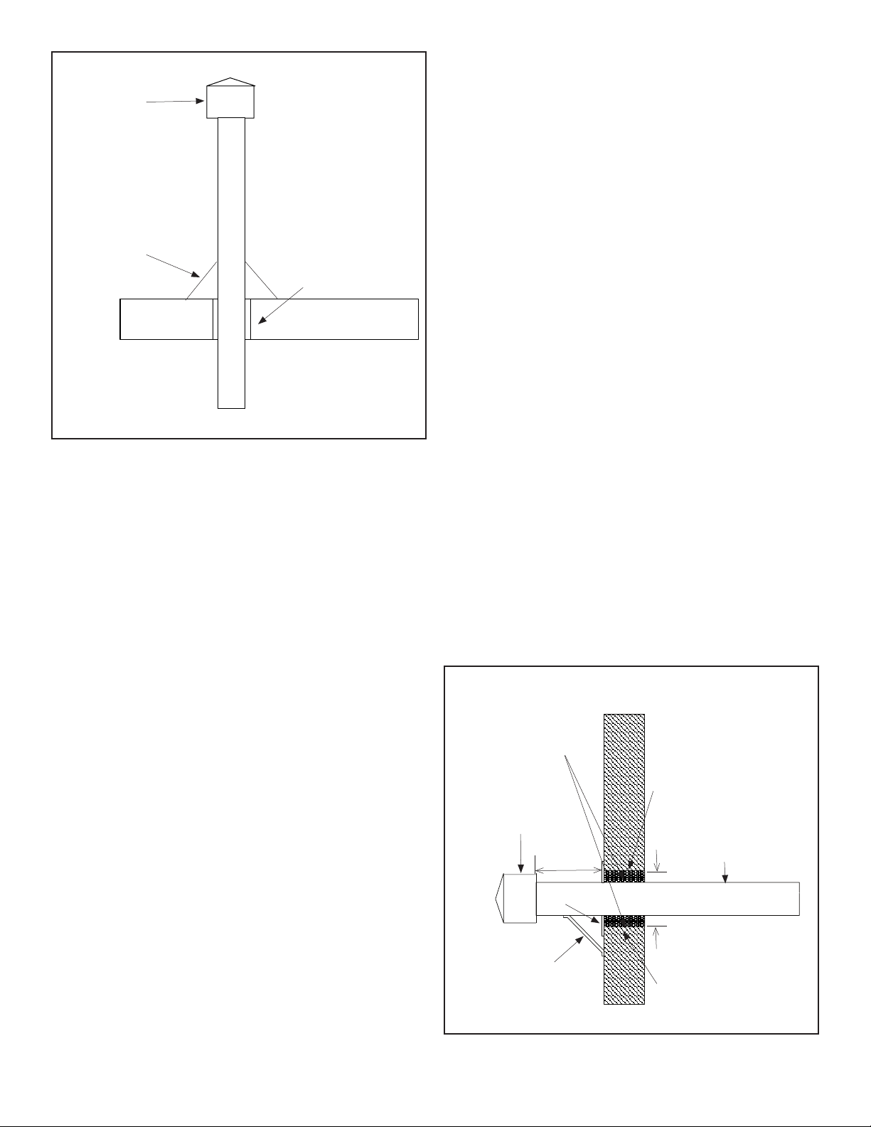
Exhaust Vent Construction Through
Combustible Walls
FIGURE 7
Fiber Glass
Insulation
Min. 2”
Vent Termination
Support Bracket
(where required)
Metal
Sleeve
Metal
Sleeve
Vent Pipe
Diameter
Metal Face
Plate
2” Min.
12” Min.
Terminal
2” Min.
Loading ...
Loading ...
Loading ...