Loading ...
Loading ...
Loading ...
Large Unit Heater
8
Operating Instructions and Owner’s Manual
• Vent must terminate a minimum of 4 feet above grade level
and must extend beyond any combustible overhang. When
condensation may be a problem, the vent system shall not
terminate over public walkways or over an area where condensate
or vapor could create a nuisance or hazard or could be
detrimental to the operation of regulators, relief openings, or
other equipment.
• The vent terminal must be installed to prevent any blockage by
snow and protect building material from degradation by flue
gases.
• The vent cap must be a minimum of 6 inches from the sidewall of
the building.
• Vent must be a minimum of 36 inches below or extend beyond
any combustible overhang.
• Consult NFPA ANSI Z223.1 Gas Vent Termination criteria for vents
that terminate on a roof pitch that exceeds 9:12.
• Canada: vents must terminate a minimum of 3 feet (914mm) from
a window or door that may be opened, and a non-mechanical air
supply inlet or combustion air inlet into the building.
TABLE 4
Vent Pipe Diameters and Equivalent Vent Pipe
Lengths for Horizontal Venting Systems
Model Vent Pipe
Diameter
Equivalent Vent Length
Minimum Maximum
MHU200NG
4” 3’ 70’
MHU250NG
6” 3’ 70’
MHU300NG
MHU400NG
General Venting Requirements
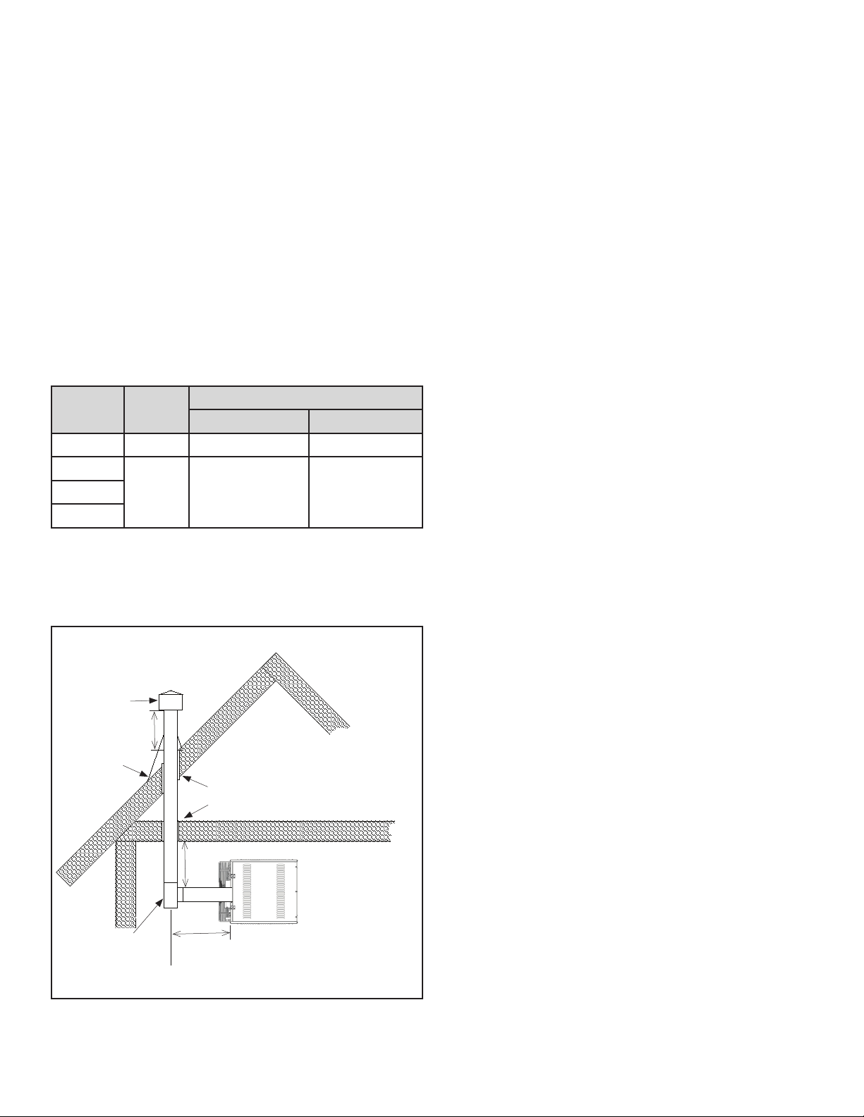
FIGURE 5
Listed Terminal
“H” Min.
4’ Min.
12” Min.
Recommended
Tee with drip leg and
cleanout cap (slope
1/4” per foot
downward toward
drip leg)
Exhaust
Roof Flashing
Use listed
thimble
through roof
and ceiling
When possible, avoid venting through an unconditioned space.
Venting through an unconditioned space promotes condensation.
When venting through an unconditioned space is unavoidable, or if
the unit is installed in an area that is prone to condensation, insulate
venting runs greater than 5 feet to minimize the production of
condensation. Inspect for leakage prior to insulating the venting and
only use insulation that is non-combustible with a temperature rating
of not less than 500��F. It is recommended that the venting system is
installed with a tee, drip leg, and clean-out cap as shown in Figure 5.
When venting pipe passes through a combustible interior wall or
floor, a metal thimble with a diameter 4 inches greater than the vent
pipe diameter must be used. If there is 6 feet or more of vent pipe
prior to passing through the combustible wall or floor, then the metal
thimble need only be 2 inches greater than the vent pipe diameter.
If a metal thimble is not used, all clearance to combustibles from the
vent pipe must be 6 inches. Where permitted, type B vent may be
used for the last section of vent pipe to reduce the required clearance
to combustibles when passing through a combustible wall or floor.
When using type B venting, follow the manufacturer’s recommended
clearance to combustibles. Any material used to close or insulate the
opening must be non-combustible.
How to attach a single wall vent terminal to double wall (Type B) vent
pipe:
1. Look for the “flow” arrow on the vent pipe.
2. Slide the vent terminal inside the exhaust end of the double wall
vent pipe.
3. Drill 3 holes through the pipe and the vent terminal. Using 3/4”
long sheet metal screws, attach the cap to the pipe. Do not
overtighten.
How to connect a single wall vent system to a double wall (Type B)
vent pipe:
1. Slide the single wall pipe inside the inner wall of the double wall
pipe.
2. Drill 3 holes through both walls of the single and double wall vent
pipes. Using 3/4” sheet metal screws, attach the 2 pieces of pipe.
Do not overtighten.
3. The gap between the single and double wall pipe must be sealed
but it is not necessary to fill the full volume of the annular area. To
seal, run a large bead of 500��F silastic around the gap.
VERTICAL VENTING
An appliance that operates with a positive vent static pressure
and with a vent gas temperature that avoids excessive condensate
production in the vent is said to be ‘Category III’. This unit heater is
considered a Category III appliance if the venting system meets all of
the following criteria:
• The vent system terminates vertically (up).
• The length of the horizontal portion of the vent run is less than 75%
of the vertical rise length. (e.g.- If the vertical vent height is 10 feet,
the horizontal run is less than 7-1/2 feet).
• Horizontal sections of the vent pipe must be installed with an
upward slope from the appliance at a pitch of 1/4 inch per foot and
suspended securely from overhead structures at points not greater
than 3’ apart.
• The vent terminates a minimum of 5 feet above the vent connection
on the unit.
Loading ...
Loading ...
Loading ...