Loading ...
Loading ...
Loading ...
Large Unit Heater
14
Operating Instructions and Owner’s Manual
ELECTRICAL REQUIREMENTS
WARNING
Shock hazard. Disconnect power supply before
making wiring connections to prevent electrical
shock and equipment damage. All appliances
must be wired strictly in accordance with wiring
diagram furnished with the appliance. Any wiring
different from the wiring diagram could result in a
hazard to persons and property.
Ensure that the supply voltage to the appliance,
as indicated on the rating plate, is not 5% greater/
less than rated voltage.
Any original factory wiring that requires replace-
ment must be replaced with wiring material hav-
ing a temperature rating of at least 221ºF (105ºC).
• Installation of wiring must conform with local building codes,
or in the absence of local codes, with the National Electric Code
ANSI/NFPA 70 - Latest Edition. Unit must be electrically grounded
in conformance to this code. In Canada, wiring must comply with
CSA C22.1, Part 1, Electrical Code.
• Two copies of the unit wiring diagram are provided with each
unit. One is located in the side access control compartment and
the other is supplied in the literature packet. Refer to this diagram
for all wiring connections.
• Make sure all multi-voltage components (motors, transformers,
etc.) are wired in accordance with the power supply voltage.
• The power supply to the unit must be protected with a fused
or circuit breaker switch, so that power can be turned off for
servicing.
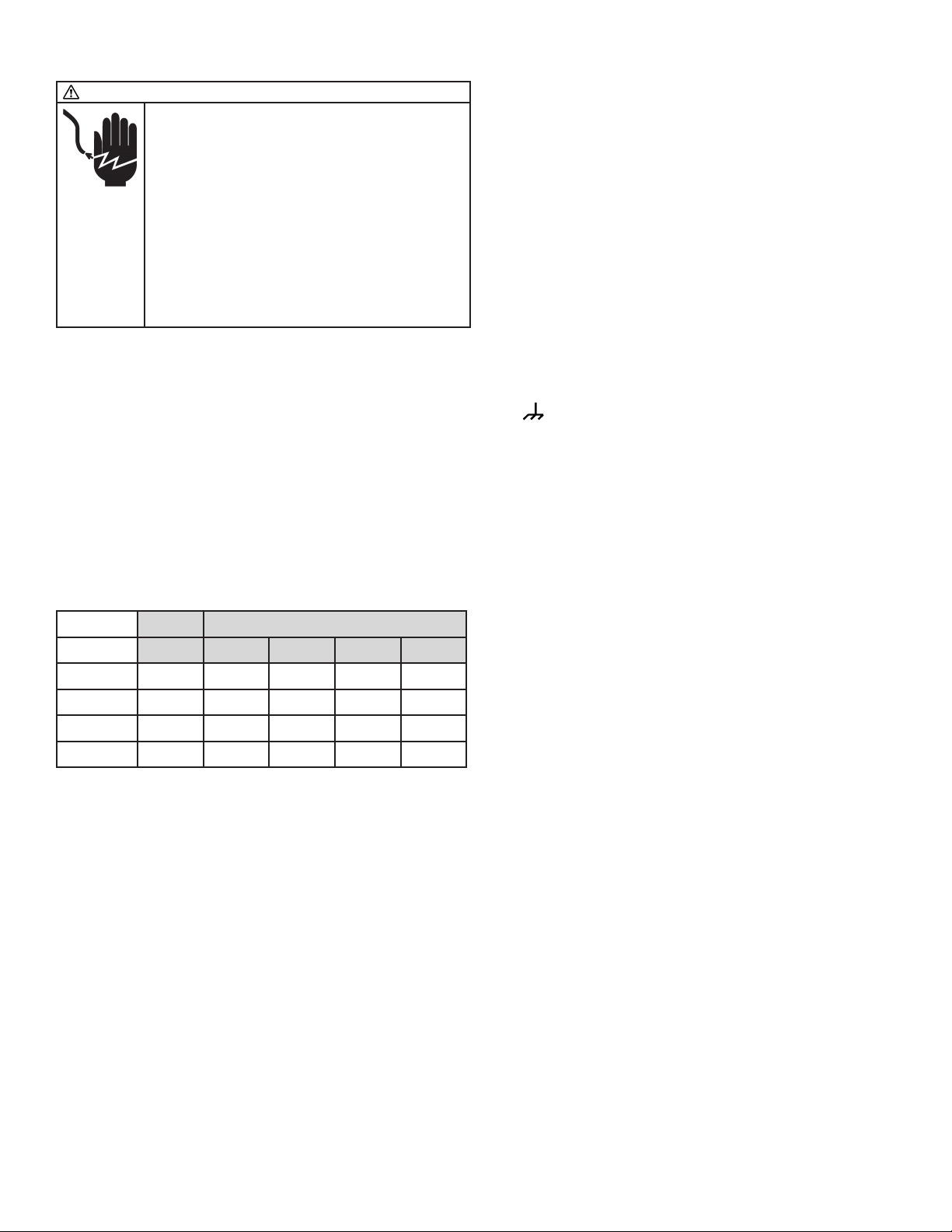
TABLE 9: Electrical Specifications
Power Supply
[V] [A] [Hz] [Ph] [W]
MHU200NG
120 6.3 60 1 756
MHU250NG
120 6.3 60 1 756
MHU300NG
120 10 60 1 1,200
MHU400NG
120 10 60 1 1,200
External electrical service connections that must be installed include:
a. Supply power connection (115, 208, 230, 460, or 575 volts).
b. Connection of thermostats, or any other accessory control devices
that may be supplied (24 volts).
All supply power electrical connections are made in the side access
control compartment of the unit. The low voltage (thermostat and
accessory control devices) can be wired to the terminals in the side
access control compartment. Refer to the wiring diagram for the
terminal location of all low voltage wiring.
NOTICE: These unit heaters use a direct spark ignition system. There
is no pilot necessary as the spark lights the main burner as the gas
valve is turned on. The direct spark ignition control board emits radio
noise during burner ignition. The level of energy may be enough to
disturb a logic circuit in a microprocessor controlled thermostat. It is
recommended that an isolation relay be used when connecting the
unit heater to a microprocessor controlled thermostat. Select circuit
protection and wire size according to the unit rating plate. Remove
electrical junction box cover and connect wiring through knockout
on the junction box located on the side of the heater. Refer to heater
wiring diagram for connection information. Use a wire for line power
connections with proper section size according to the electrical power
data indicated in Table 9 and its length. Make sure to connect line
power to wires located in the external electrical junction box behind
junction box cover. DO NOT CONNECT LINE POWER TO THERMOSTAT
TERMINAL STRIP ON OUTSIDE OF HEATER.
Electrically ground the unit in accordance with local codes or in the
absence of local codes, in accordance with the current National
Electrical Code (ANSI/NFPA No. 70) in the USA, and in Canada with
the current Canadian Electrical Code, Part 1 CSA C22.1.
Un-insulated ground wire must be wrapped in electrical tape to avoid
damage to the electrical system.
• Make line voltage connections as shown in Figure 10. Connect
field wiring as shown on wiring diagram on unit. Also, refer to
typical diagram in this manual.
• To use the blower for air circulation only, your thermostat must
have a “fan only” or fan selection setting. In case your thermostat
has this option, an additional wire should be run to the
“ ”terminal on the thermostat connection block. See wiring
schematic in Figure 11 .
Loading ...
Loading ...
Loading ...