Loading ...
Loading ...
Loading ...
Large Unit Heater
10
Operating Instructions and Owner’s Manual
Additional requirements for horizontal venting:
• Category III venting systems may NOT be common vented, and no
other gas units are allowed to be vented into it.
• Vent must terminate a minimum of 3 feet (914mm) above any
forced air inlet that is located within 10 feet.
• The bottom of the vent terminate must be located a minimum
of 12 inches above grade level and must extend beyond any
combustible overhang.
• When horizontally vented, minimum clearance for termination
from any door, window, gravity air inlet, gas or electric
meter, regulators, and relief equipment is 4 ft. (1.2m) for U.S.
installations. Refer to NFPA 54/ANSI Z223.1 in the U.S.A. and
CSA B149.1 Natural Gas and Propane Installation Code and .2 in
Canada or with authorities having local jurisdiction. In Canada,
vent termination must have a minimum 6 ft. (1.8 m) horizontal
clearance from gas and electric meters and relief devices as
specified in the Canadian B149.1, Natural Gas Installation Code.
• Never join two sections of double wall vent pipe within one
horizontal vent system, as it is impossible to verify that inner pipes
are completely sealed.
• For a vent termination located under an eave, the distance of the
overhang must be at least 24”. The clearance to combustibles
above the exterior vent must be maintained at a minimum of 12”.
Consult the National Fuel Gas Code for additional requirements
for eaves that have ventilation openings.
• For horizontal venting, the vent pipe shall be supported with
hangers no more than 3ft.(1m) apart to prevent movement after
installation.
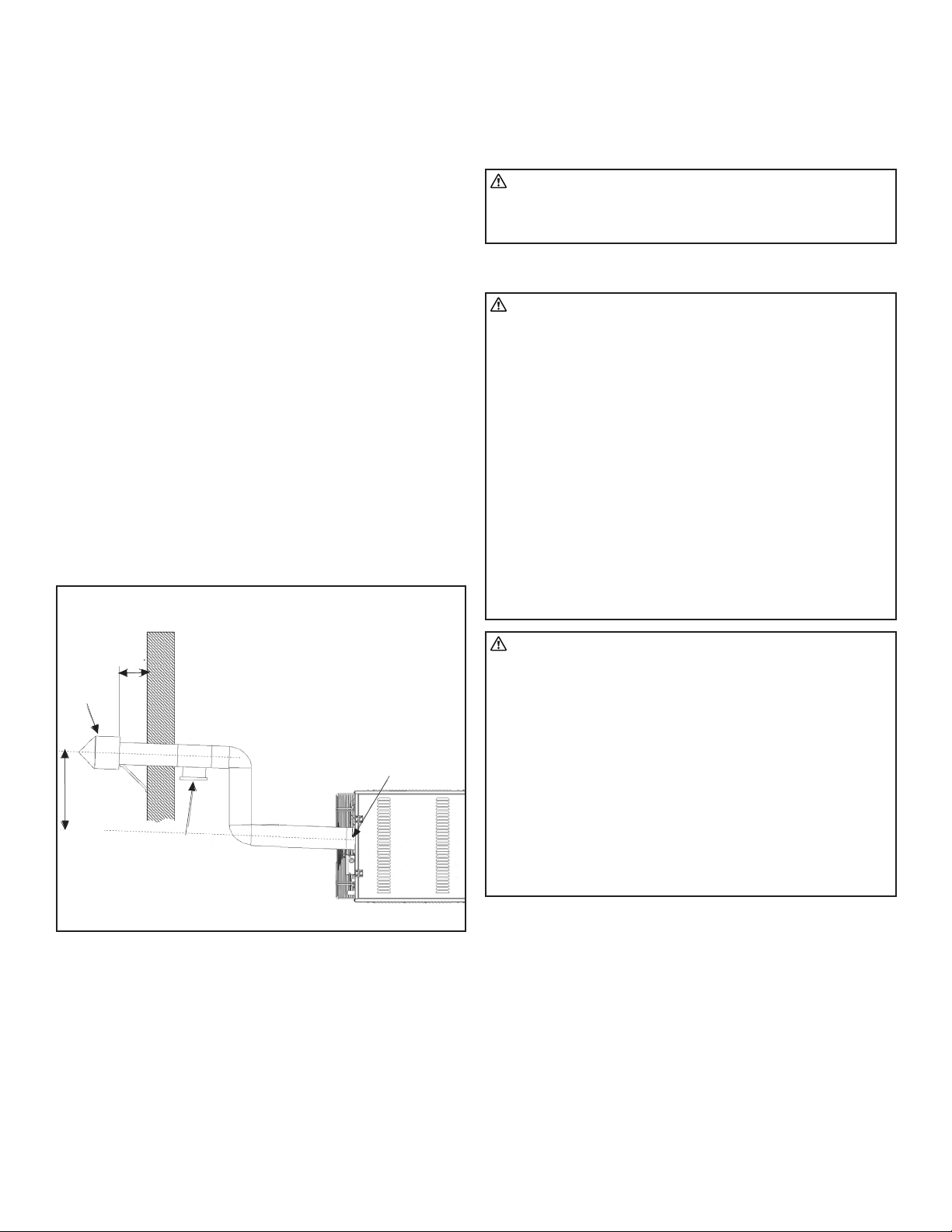
The Horizontal Run
of Vent Pipe Shall
be Pitched Upward
1/ 4 IN. to the FT.
(21 MM to the M).
Power
Exhauster
Outlet
5 ft.
Min.
12”
Min.
Terminal
Tee with Drip Leg and
Cleanout Cap at Low
Point of Vent System
Horizontal Venting
FIGURE 8
COMBUSTION AIR REQUIREMENTS
Adequate facilities for supplying air for combustion and ventilation
must be provided in accordance with the latest edition of section 5.3,
Air for Combustion and Ventilation, of the National Fuel Gas Code,
ANSI Z223.1, in the U.S.A., CSA B149.1 Natural Gas and Propane Instal-
lation Code, the National Standards of Canada or applicable provisions
of local building codes.
All gas fired appliances require air to be used for the combustion
process. In many buildings today, there is a negative indoor air pressure
caused by exhaust fans, etc. If sufficient quantities of combustion air
are not available, the heater or another appliance will operate in an in-
efficient manner, resulting in incomplete combustion which can result
in the production of excessive carbon monoxide.
Follow these guidelines and all applicable codes for all models prior to
installing the combustion air duct work.
WARNING: Sufficient combustion air must be supplied
to the appliance at all times. Lack of combustion air may
result in property damage, headaches, nausea, dizziness,
asphyxiation, serious injury, or death.
GAS CONNECTIONS
WARNING: Danger of explosion and fire. Improperly
connected gas lines may result in serious injury and death,
explosion, poisonous fumes, toxic gases, or asphyxiation.
Connect gas lines in accordance to national, state, provincial,
and local codes.
This heater burns natural gas or liquefied petroleum (LP) gas
and is equipped with a regulator. The regulator is built into
the gas valve. The maximum inlet pressure to this regulator
is 20 in. W.C.. If gas line pressure exceeds 20 in. W.C., then
an additional regulator must be installed before the heater/
regulator to step down the pressure to a maximum of 20 in.
W.C..
All field gas piping must be pressure/leak tested prior to
operation. Never use an open flame. Use a soap solution or
equivalent for testing.
You must follow these instructions exactly. If over-heating
occurs or if gas supply fails to shut off, shut off the manual
gas valve to the appliance before shutting off electrical
supply.
CAUTION: Gas lines should be purged of air as described
in ANSI Z223.1 (NFPA 54) or CSA-B149.1– latest version.
Installation of the piping must also conform with the local
building codes, or in the absence of local codes, with the
latest edition of the National Fuel Gas Code (NFPA 54). In
Canada, installation must be in accordance with CSA-B149.1.
When leak testing the gas supply piping system, the
appliance and its combination gas control must be isolated
during any pressure testing in excess of 14” W.C. (1/2 psi).
The unit should be isolated from the gas supply piping
system by closing its field installed manual shut-off valve.
This manual shut-off valve should be located within 6’ of the
heater.
Turn off all gas before installing appliance
NOTICE: The total input to the appliance must fall within +/- 5% of
the rated input as indicated on the rating plate. Otherwise the heat
exchanger may prematurely fail.
All piping installed must comply with local codes and ordinances or
with National Fuel Gas Code, ANSI Z223.1 (NFPA 54), whichever takes
precedence. When installing piping, the following requirements must
be taken into consideration: Canadian installations must comply with
the B149.1.2 Gas Code.
• Use new properly reamed black pipe free from chips.
• Apply a good quality pipe compound to all male threads prior
to assembly. If LP gas is the fuel, ensure that pipe compound is
resistant to LP gas. Do not use Teflon™ tape.
Loading ...
Loading ...
Loading ...