Loading ...
Loading ...
Loading ...
7
GB
B
D
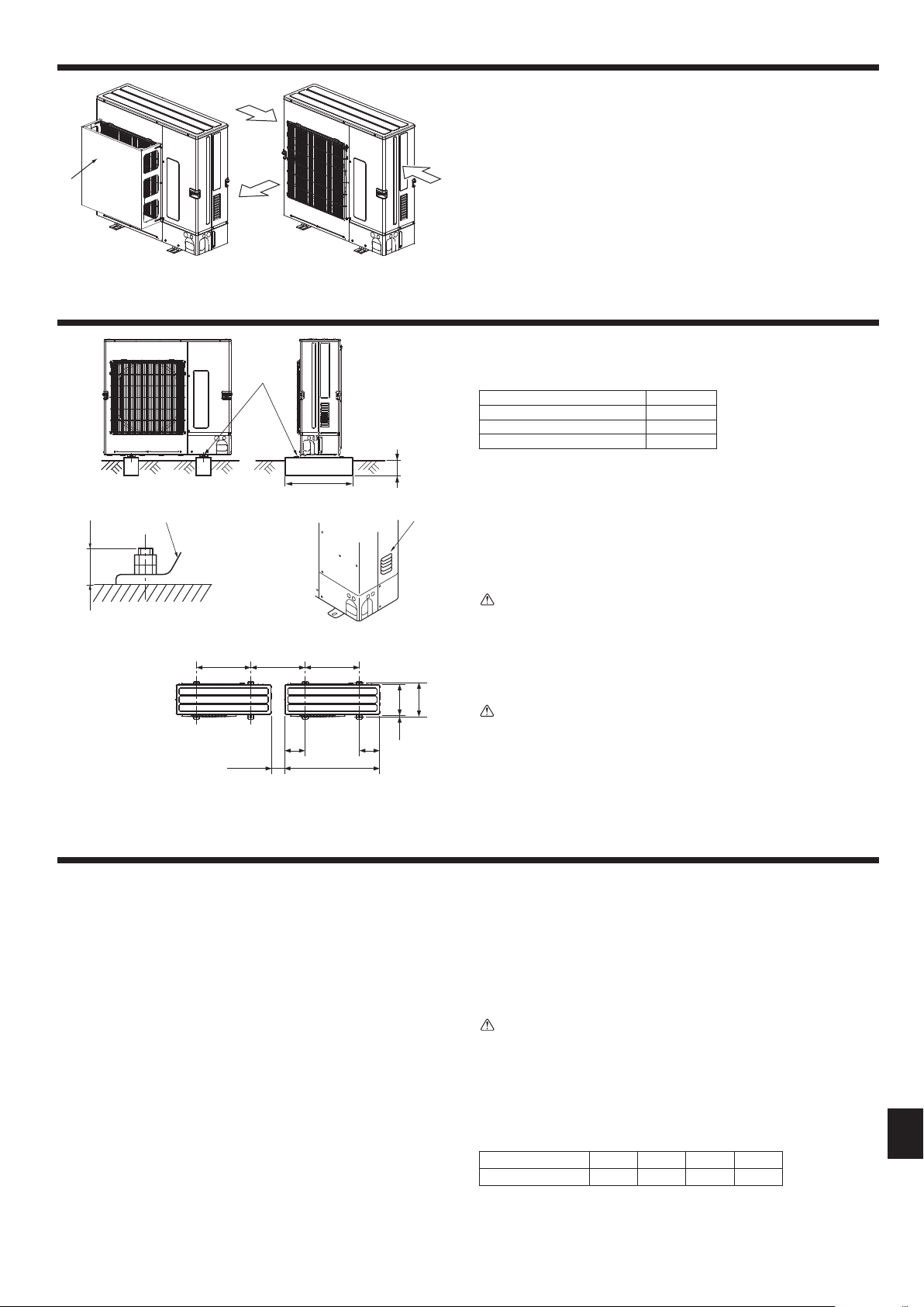
600 600
33025
370
225 225
1050
2.5.3. Windylocationinstallation
When installing the outdoor unit on a rooftop or other location unprotected from the
wind, situate the air outlet of the unit so that it is not directly exposed to strong winds.
Strongwindenteringtheairoutletmayimpedethenormalairowandamalfunction
may result.
The following shows two examples of precautions against strong winds.
1 Install an optional air guide if the unit is installed in a location where strong winds
from a typhoon, etc. may directly enter the air outlet. (Fig. 2-15)
A Air guide
2 Position the unit so that the air outlet blows perpendicularly to the seasonal wind
direction, if possible. (Fig. 2-16)
B Wind direction
2. Installationlocation
3. Installingtheoutdoorunit
• Besuretoinstalltheunitinasturdy,levelsurfacetopreventrattlingnoisesduring
operation. (Fig. 3-1)
<Foundationspecications>
Foundation bolt M10(3/8″)
Thickness of concrete 120 mm
Length of bolt 70 mm
Weight-bearing capacity 320 kg
• Makesurethatthelengthofthefoundationboltiswithin30mmofthebottomsurface
of the base.
• Securethebaseoftheunitrmlywithfour-M10foundationboltsinsturdylocations.
Installing the outdoor unit
• Donotblockthevent.Iftheventisblocked,operationwillbehinderedandbreak-
down may result.
• Inadditiontotheunitbase,usetheinstallationholesonthebackoftheunittoattach
wires,etc.,ifnecessarytoinstalltheunit.Useself-tappingscrews(ø5× 15 mm or
less) and install on site.
Warning:
• Theunitmustbesecurelyinstalledonastructurethatcansustainitsweight.
Iftheunitismountedonanunstablestructure,itmayfalldownandcause
damageorinjuries.
• Theunitmustbeinstalledaccordingtotheinstructionsinordertominimize
theriskofdamagefromearthquakes,typhoons,orstrongwinds.Anincor-
rectlyinstalledunitmayfalldownandcausedamageorinjuries.
Caution:
• Installunitonarigidstructuretopreventexcessiveoperationsoundorvibra-
tion.
Fig.3-1
4. Installingtherefrigerantpiping
4.1. PrecautionsfordevicesthatuseR410Arefrigerant
• Referto1.5.forprecautionsnotincludedbelowonusingairconditionerswith
R410Arefrigerant.
• Useesteroil,etheroil,alkylbenzeneoil(smallamount)astherefrigeration
oilappliedtothearedsections.
• UseC1220copperphosphorus,forcopperandcopperalloyseamlesspipes,
toconnecttherefrigerantpipes.Userefrigerantpipeswiththethicknesses
speciedinthetabletothebelow.Makesuretheinsidesofthepipesareclean
anddonotcontainanyharmfulcontaminantssuchassulfuriccompounds,
oxidants,debris,ordust.
Warning:
When installing or relocating, or servicing the air conditioner,use only the
speciedrefrigerant(R410A)tochargetherefrigerantlines.Donotmixitwith
anyotherrefrigerantanddonotallowairtoremaininthelines.
Ifairismixedwiththerefrigerant,thenitcanbethecauseofabnormalhigh
pressureintherefrigerantline,andmayresultinanexplosionandotherhazards.
Theuseofanyrefrigerantotherthanthatspeciedforthesystemwillcause
mechanicalfailureorsystemmalfunctionorunitbreakdown.Intheworstcase,
thiscouldleadtoaseriousimpedimenttosecuringproductsafety.
Pipe size (mm) ø6.35 ø9.52 ø12.7 ø15.88
Thickness (mm) 0.8 0.8 0.8 1.0
• Donotusepipesthinnerthanthosespeciedabove.
• ThethicknesseslistedinthetableabovearebasedonJapanesestandards.
Usepipeswithamaximumworkingpressureof4.15MPa[601PSIG]or
higheraccordingtolocalstandards.
AM10(3/8")bolt
B Base
C As long as possible.
(mm)
D Vent
E Set deep in the ground.
Min. 500
Min. 25*
* When installing a single outdoor unit, the clearance is 15 mm or more.
Max. 30
Fig.2-15 Fig.2-16
B
A
E
C
A
RG79Y960H01.indb 7 2018/02/09 14:31:04
Loading ...
Loading ...
Loading ...