Loading ...
Loading ...
Loading ...
14
GB
4. Installingtherefrigerantpiping
4.6. Additionalrefrigerantcharge
Additionalrefrigerantcharge
Refrigerant for the extended piping is not included in the outdoor unit when the unit is
shipped from the factory. Therefore, charge each refrigerant piping system with addi-
tional refrigerant at the installation site. In addition, in order to carry out service, enter
the size and length of each liquid pipe and additional refrigerant charge amounts in
the spaces provided on the “Refrigerant amount” plate on the outdoor unit.
Calculationofadditionalrefrigerantcharge
• Calculate the additional charge using the liquid pipe size and length of the ex-
tended piping.
• Calculate the additional refrigerant charge using the procedure shown to the
right, and charge with the additional refrigerant.
• For amounts less than 0.1kg,roundup the calculated additional refrigerant
charge.
(For example, if the calculated charge is 32.92 kg, round up the charge to 33.0
kg.)
<AdditionalCharge>
Calculationofrefrigerantcharge
Pipe size
Liquid pipe
+
Pipe size
Liquid pipe
+
Total capacity of
connected indoor units
Amount for the
indoor units
ø6.35 ø9.52 ~ 8.0 kW 1.5 kg
(m) ×19.0(g/m) (m) ×50.0(g/m) 8.1 ~ 16.0 kW 2.5 kg
16.1 ~ 20.4 kW 3.0 kg
Includedrefrigerantamountwhenshippedfromthefactory
Included refrigerant amount
3.5 kg
Calculationexample(PleaseseethelowerhalfofFig.4-1.)
Outdoormodel:SP140 A:ø9.52[3/8"]/ø
15.88
[
5/8"
]:30m
1: P100 (11.2 kW)
a:ø9.52[3/8"]/ø15.88[5/8"]
:
15 m
2: P40 (4.5 kW)
b:ø6.35[1/4"]/ø12.7[1/2"]
:
10 m
The total length of each pipe size is as follows:
ø9.52
[3/8
"
]/
ø
15.88
[
5/8"
]:A=30m
ø9.52
[3/8
"
]/
ø15.88
[5/8"]
: a = 15 m
ø6.35
[1/4
"
]/
ø12.7
[1/2
"
]
: b = 10 m
The total capacity of connected indoor unit is as follows:
11.2 + 4.5 = 15.7
Therefore, the additional charge is as follows:
= 10 ×
19.0
+ (30 + 15) ×
50.0
+ 2.5
1000 1000
= 5.0 kg
For these
piping
lengths
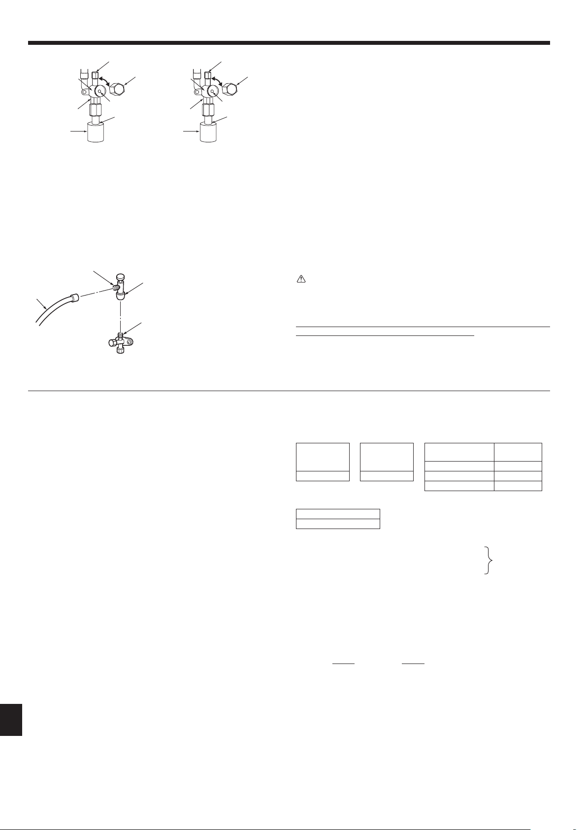
4.5.Stopvalveopeningmethod
Thestopvalveopeningmethodvariesaccordingtotheoutdoorunitmodel.Usethe
appropriate method to open the stop valves.
(1) Gas side (Fig. 4-12)
1 Remove the cap and turn the valve rod counterclockwise as far as it will go with
the use of a 5 mm hexagonal wrench. Stop turning when it hits the stopper.
(ø15.88:Approximately13revolutions)
2 Make sure that the stop valve is open completely and rotate the cap back to its
original position.
(2) Liquid side (Fig. 4-13)
1 Remove the cap and turn the valve rod counterclockwise as far as it will go with
the use of a 4 mm hexagonal wrench. Stop turning when it hits the stopper.
(ø9.52:Approximately10revolutions)
2 Make sure that the stop valve is open completely, push in the handle and rotate
the cap back to its original position.
Refrigerant pipes are protectively wrapped
• Thepipescanbeprotectivelywrappeduptoadiameterofø90beforeoraftercon-
necting the pipes. Cut out the knockout in the pipe cover following the groove and
wrap the pipes.
Pipe inlet gap
• Useputtyorsealanttosealthepipeinletaroundthepipessothatnogapsremain.
(If the gaps are not closed, noise may be emitted or water and dust will enter the
unit and breakdown may result.)
Warning:
Wheninstallingtheunit,securelyconnecttherefrigerantpipesbeforestarting
thecompressor.
Precautionswhenusingthechargevalve(Fig.4-14)
Do not tighten the service port too much when installing it, otherwise, the valve core
could be deformed and become loose, causing a gas leak.
After positioning section B in the desired direction, turn section A only and tighten it.
Do not further tighten sections A and B together after tightening section A.
B
C
A
D
* The gure to the left is an example
only. The stop valve shape, service port
position, etc., may vary according to the
model.
* Turn section A only.
(Do not further tighten sections A and
B together.)
C Charge hose
D Service port
Fig.4-14
Fig.4-12 Fig.4-13
H Double spanner section
(Do not apply a spanner other than to this section. Doing
so would cause coolant leaks.)
I Seal section
(Seal the end of the heat insulation material at the pipe
connection section with whatever seal material you
haveonhandsothatwaterdoesnotinltratetheheat
insulation material.)
A Valve
B Unitside
C Cap
D Local pipe side
E Pipe cover
F Service port
G Wrench hole
(1) (2)
H H
E E
F F
A A
G G
I I
D D
C C
B B
RG79Y960H01.indb 14 2018/02/09 14:31:08
Loading ...
Loading ...
Loading ...