Loading ...
Loading ...
Loading ...
16
GB
Exampleofagroupoperationsystemwithmultipleoutdoorunits(Shieldingwiresandaddresssettingarenecessary.)
<ExamplesofTransmissionCableWiring>
■ RefertoFig.6-6fromFig.6-2.
<WiringMethodandAddressSettings>
a. Always use shielded wire when making connections between the outdoor unit (OC) and the indoor unit (IC), as well for all OC-OC, and IC-IC wiring intervals.
b. UsefeedwiringtoconnectterminalsM1andM2andthegroundterminalonthetransmissioncableterminalblock(TB3)ofeachoutdoorunit(OC)toterminalsM1,M2
and terminal S on the transmission cable block of the indoor unit (IC).
c. Connect terminals 1 (M1) and 2 (M2) on the transmission cable terminal block of the indoor unit (IC) that has the most recent address within the same group to the terminal
block on the remote controller (RC).
d. Connect together terminals M1, M2 and terminal S on the terminal block for centralized control (TB7) for the outdoor unit (OC).
e. ThejumperconnectorCN41onthecontrolpaneldoesnotchange.
f.
Connect shield ground of the indoor units transmission line to the shield (S) terminal of (TB3) and also connect (S) terminal to the screw (E or F) using attached lead wire.
Connect shield ground of the line between outdoor units and the centralized control system transmission line to the shield (S) terminal of (TB7).
g. Set the address setting switch as follows.
Unit Range Setting Method
M-IC (Main) 01 to 50 Usethemostrecentaddresswithinthesamegroupofindoorunits
M-IC (Sub) 01 to 50
Useanaddress,otherthanthatoftheIC(Main)fromamongtheunitswithinthesamegroupofindoorunits.Thismustbe
in sequence with the IC (Main)
Outdoor unit 51 to 100
Usethemostrecentaddressofalltheindoorunitsplus50
* The address automatically becomes “100” if it is set as “01 - 50”.
M-NETRC(Main)*1 101 to 150 Set at an IC (Main) address within the same group plus 100
M-NETRC(Sub)*1 151 to 200 Set at an IC (Main) address within the same group plus 150
MA RC — Unnecessaryaddresssetting(Necessarymain/subsetting)
*1 An ME remote controller cannot be connected to a system that contains a branch box.
h. Thegroupsettingoperationsamongthemultipleindoorunitsisdonebytheremotecontroller(M-NETRC)aftertheelectricalpowerhasbeenturnedon.
<PermissibleLengths>
1
M-NETRemotecontroller
• Maxlengthviaoutdoorunits:L
1
+L
2
+L
3
+L
4
and L
1
+L
2
+L
3
+L
5
and L
1
+L
2
+L
6
+L
7
[
500 m (1.25 mm² or more)
• Maxtransmissioncablelength:L
1
and L
3
+L
4
and L
3
+L
5
and L
2
+L
6
and L
7
[
200 m (1.25 mm² or more)
• Remotecontrollercablelength:
r
1
,
r
2
,
r
2
+
r
3
,
r
4
[
10 m (0.5 to 1.25 mm²)
If the length exceeds 10 m, use a 1.25 mm² shielded wire. The length of this section (L
8
) should be included in the calculation of the
maximum length and overall length.
2
MARemotecontroller
• Maxlengthviaoutdoorunit(M-NETcable):L
1
+L
2
+L
3
+L
4
and L
1
+L
2
+L
6
+L
7
[
500 m (1.25 mm² or more)
• Maxtransmissioncablelength(M-NETcable):L
1
and L
3
+L
4
and L
2
+L
6
and L
7
[
200 m (1.25 mm² or more)
• Remotecontrollercablelength:
c
1
and
c
1
+
c
2
+
c
3
and
c
1
+
c
2
+
c
3
+
c
4
[
200 m (0.3 to 1.25 mm²)
6. Electricalwork
6.3. Wiringtransmissioncables
1 Typesofcontrolcables
1. Wiring transmission cables
• Typesoftransmissioncables:ShieldingwireCVVS,CPEVSorMVVS
• Cablediameter:Morethan1.25mm
2
• Maximumwiringlength:Within200m
2. M-NETRemotecontrolcables
Kind of remote control cable Shielding wire CVVS, CPEVS or MVVS
Cable diameter 0.5 to 1.25 mm
2
(0.75 to 1.25 mm
2
)*
Remarks
When 10 m is exceeded, use cable with the same
specicationsastransmissionlinewiringcables.
* Connected with simple remote controller.
3. MA Remote control cables
Kind of remote control cable Sheathed 2-core cable (unshielded) CVV
Cable diameter 0.3 to 1.25 mm
2
(0.75 to 1.25 mm
2
)*
Remarks Within 200 m
* Connected with simple remote controller.
2 Wiringexamples
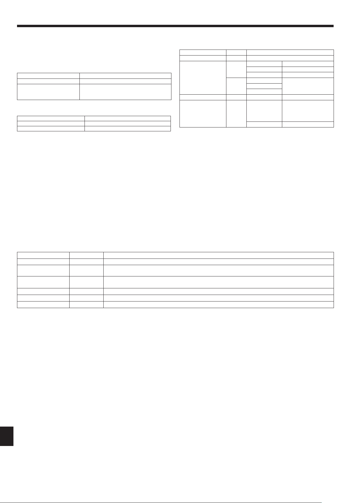
• Controllername,symbolandallowablenumberofcontrollers.
Name Symbol Allowable number of controllers
Outdoor unit controller OC –
Indoor unit controller
M-IC
PUMY-SP112 1 to 9 units per 1 OC *1
PUMY-SP125 1 to 10 units per 1 OC *1
PUMY-SP140 1 to 12 units per 1 OC *1
A-IC
PUMY-SP112
2 to 8 units per 1 OC *1PUMY-SP125
PUMY-SP140
Branch box – – 0 to 2 units per 1 OC
Remote controller RC
M-NETRC*2,*3
Maximum of 12 control-
lers for 1 OC (Can not be
connected if Branch box
is used.)
MA-RC Maximum of 2 per group
Note:
*1. Thenumberofconnectableunitsmaybelimitedbysomeconditionssuch
asanindoorunit’scapacityoreachunit’sequivalentpowerconsumption.
*2. Don’tusetheLossnaycontroller(PZ-61DR-E,PZ-43SMF-E,PZ-52SF-E,
PZ-60DR-E).
*3. AnMEremotecontrollercannotbeconnectedtoasystemthatcontains
abranchbox.
RG79Y960H01.indb 16 2018/02/09 14:31:09
Loading ...
Loading ...
Loading ...