Loading ...
Loading ...
Loading ...
4
GB
2. Installationlocation
2.1. Refrigerantpipe
Refer to Fig. 4-1, 4-2.
2.2. Choosingtheoutdoorunitinstallationlocation
• Avoidlocationsexposedtodirectsunlightorothersourcesofheat.
• Selectalocationfromwhichnoiseemittedbytheunitwillnotinconvenienceneigh-
bors.
• Selectalocationpermittingeasywiringandpipeaccesstothepowersourceand
indoor unit.
• Avoidlocationswherecombustiblegasesmayleak,beproduced,ow,oraccumu-
late.
• Notethatwatermaydrainfromtheunitduringoperation.
• Selectalevellocationthatcanbeartheweightandvibrationoftheunit.
• Avoidlocationswheretheunitcanbecoveredbysnow.Inareaswhereheavysnow
fall is anticipated, special precautions such as raising the installation location or
installing a hood on the air intake must be taken to prevent the snow from block-
ingtheairintakeorblowingdirectlyagainstit.Thiscanreducetheairowanda
malfunction may result.
• Avoidlocationsexposedtooil,steam,orsulfuricgas.
• Usethetransportationhandlesoftheoutdoorunittotransporttheunit.Iftheunit
iscarriedfromthebottom,handsorngersmaybepinched.
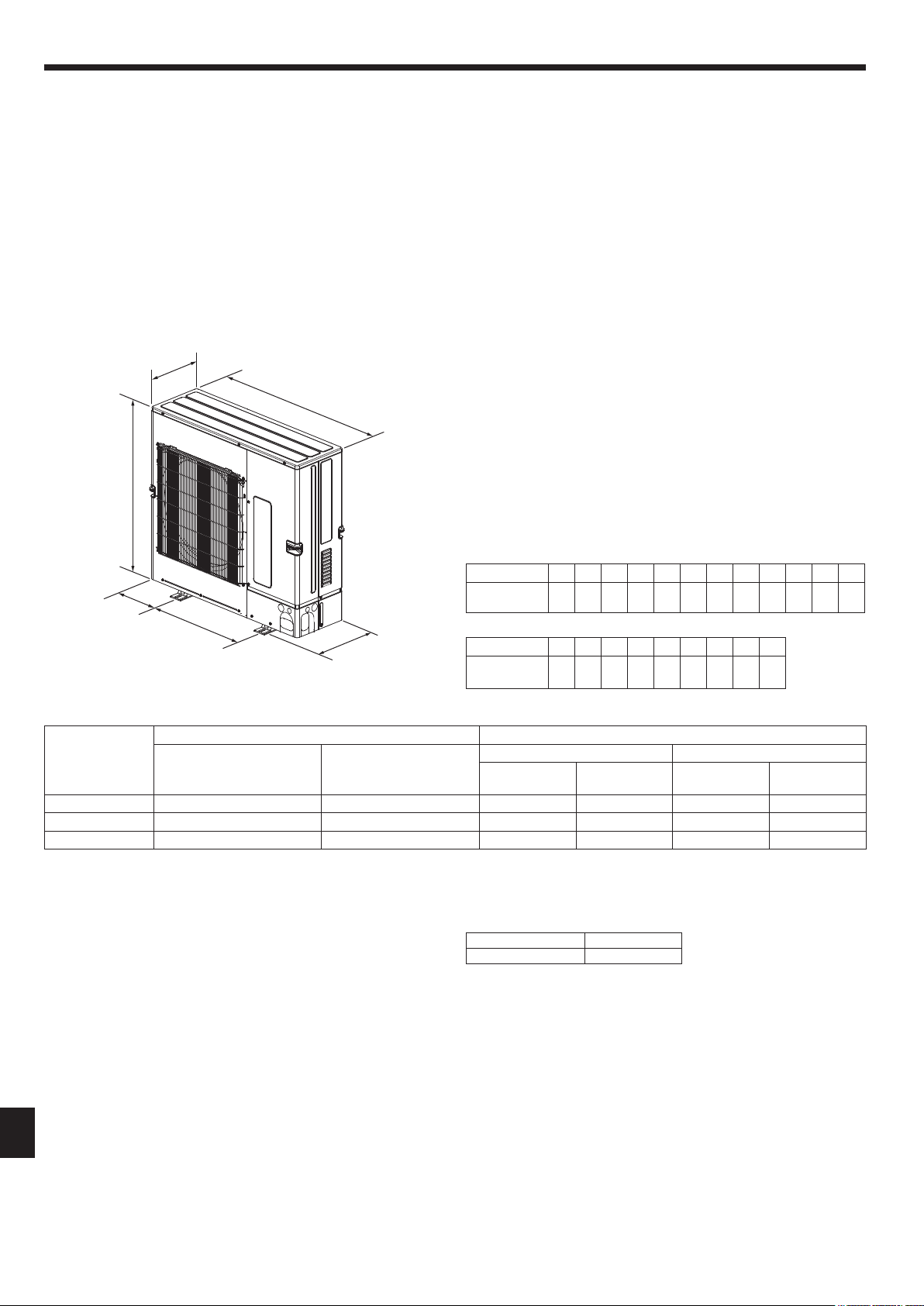
2.3. Outlinedimensions(Outdoorunit)(Fig.2-1)
Constraints on indoor unit installation
You should note that indoor units that can be connected to this outdoor unit are the
following models.
• Indoorunitswithmodelnumbers15-140canbeconnected.
When using Branch box, Indoor units with model numbers 22-100 can be connected.
Refer to the table 1 below for possible room, indoor unit combinations.
Verication
The rated capacity should be determined by observing the table below. The unit’s
quantities are limited as shown in the following table 2. For the next step, make
sure that the total rated capacity selected will stay in a range of 50% – 130% of the
outdoor unit capacity.
• PUMY-SP112 6.3–16.2kW
• PUMY-SP125 7.1–18.2kW
• PUMY-SP140 8.0–20.2kW
Table 1-1 City Multi indoor units
Indoor unit type
15 20 25 32 40 50 63 71 80 100 125 140
Rated capacity
(Cooling) (kW)
1.7 2.2 2.8 3.6 4.5 5.6 7.1 8.0 9.0 11.2 14.0 16.0
Table 1-2 M series, P series, S series
Indoor unit type
22 25 35 42 50 60 71 80 100
Rated capacity
(Cooling) (kW)
2.2 2.5 3.5 4.2 5.0 6.0 7.1 8.0 10.0
Table 2 Connectable indoor units quantities
Model Only system Mixed system
Only City Multi indoor units
(Connection without Branch box)
Only M series, P series,
S series indoor units
(Connection with Branch box)
One Branch box Two Branch box
Connection with
Branch box
City Multi indoor
units
Connection with
Branch box
City Multi indoor
units
PUMY-SP112 1-9 2-8 Max. 5 Max. 5 Max. 7 or 8*1 Max. 3 or 2*1
PUMY-SP125 1-10 2-8 Max. 5 Max. 5 Max. 8 Max. 3
PUMY-SP140 1-12 2-8 Max. 5 Max. 5 Max. 8 Max. 3
(mm)
Fig.2-1
370
1050
225
600
981
330+25
*1 When connecting 7 indoor units via branch box, connectable citymulti indoor units
are 3; connecting 8 indoor units via branch box, connectable citymulti indoor units
are 2.
Table 3 Connectable Branch box quantities
Model Branch box
PUMY-SP112/125/140 1-2
Combinations in which the total capacity of indoor units exceeds the capacity of the
outdoor unit will reduce the cooling capacity of each indoor unit below their rated
cooling capacity. Thus, combine indoor units with an outdoor unit within the outdoor
unit’s capacity, if possible.
RG79Y960H01.indb 4 2018/02/09 14:30:59
Loading ...
Loading ...
Loading ...