Loading ...
Loading ...
Loading ...
12
GB
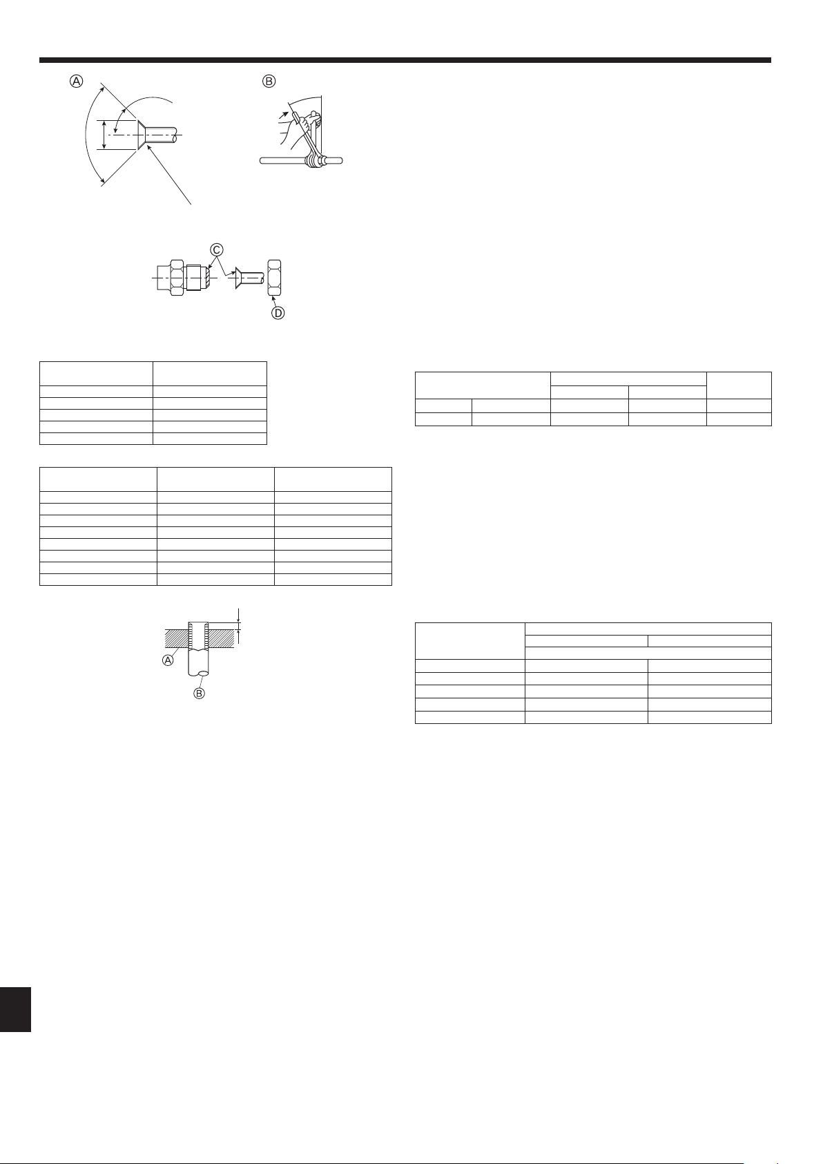
A Flare cutting dimensions
B Flare nut tightening torque
A Die
B Copper pipe
Fig.4-8
A
Fig.4-9
A (Fig. 4-8)
B (Fig. 4-8)
90°± 0.5°
øA
45°± 2°
R0.4 - R0.8
Copper pipe O.D.
(mm)
Flare dimensions
øAdimensions(mm)
ø6.35 8.7 - 9.1
ø9.52 12.8 - 13.2
ø12.7 16.2 - 16.6
ø15.88 19.3 - 19.7
ø19.05 23.6 - 24.0
Copper pipe O.D.
(mm)
Flare nut O.D.
(mm)
Tightening torque
(N·m)
ø6.35 17 14 - 18
ø6.35 22 34 - 42
ø9.52 22 34 - 42
ø12.7 26 49 - 61
ø12.7 29 68 - 82
ø15.88 29 68 - 82
ø15.88 36 100 - 120
ø19.05 36 100 - 120
4.2. Connectingpipes(Fig.4-8)
Fig. 4-1, 4-2 is a sample of piping system.
• Conductsufcientanti-condensationandinsulationworktopreventwaterdripping
fromtherefrigerantpiping.(liquidpipe/gaspipe)
• Increase insulation depending on the environment where the refrigerant piping
is installed, or condensation may occur on the surface of the insulation material.
(Insulation material Heat-resistant temperature: 120 °C, Thickness: 15 mm or more)
* When the refrigerant piping is used in locations subject to high temperature and
humidity such as in the attic, further addition of insulation may be required.
• Toinsulatetherefrigerantpiping,applyheat-resistantpolyethylenefoambetween
the indoor unit and insulation material as well as to the net between the insulation
materialllingallgaps.
(Condensation forming on the piping may result in condensation in the room or
burns when contacting the piping.)
• Besuretoseparatethermalinsulationforgasandliquidrefrigerantpipes.
• Theindoorpartsofthedrainpipeshouldbewrappedwithpolyethylenefoaminsula-
tionmaterials(specicgravityof0.03,thicknessof9mmormore).
• Applythinlayerofrefrigerantoiltopipeandjointseatingsurfacebeforetightening
arenut.A
• Use2wrenchestotightenpipingconnections.B
• Use leak detector or soapy water to check for gas leaks after connections are
completed.
• Applyrefrigeratingmachineoilovertheentireareseatsurface.C
• Usethearenutsforthefollowingpipesize.D
City Multi Indoor unit
Outdoor unit
15-50 63-140
Gas side Pipe size (mm) ø12.7 ø15.88 ø15.88
Liquid side Pipe size (mm) ø6.35*1 ø9.52 ø9.52
*1 Ifthefarthestpipinglengthaftertherstjointexceeds30m,useapipesizeofø9.52.
• When bending the pipes, be careful not to break them. Bend radius of 100 mm to
150mmissufcient.
• Make sure the pipes do not contact the compressor. Abnormal noise or vibration
may result.
1 Pipes must be connected starting from the indoor unit.
Flare nuts must be tightened with a torque wrench.
2 Flare the liquid pipes and gas pipes and apply a thin layer of refrigeration oil (Ap-
plied on site).
• Whenusualpipesealingisused,refertoTable3foraringofR410Arefrigerant
pipes.
ThesizeadjustmentgaugecanbeusedtoconrmAmeasurements.
* Toconnectthe CONNECTIONKIT(PAC-LV11M-J),refertotheinstallation
manualfortheCONNECTIONKIT.
Table 3 (Fig. 4-9)
Copper pipe O.D.
(mm)
A (mm)
Flare tool for R410A Flare tool for R22·R407C
Clutch type
ø6.35(1/4") 0 - 0.5 1.0 - 1.5
ø9.52(3/8") 0 - 0.5 1.0 - 1.5
ø12.7(1/2") 0 - 0.5 1.0 - 1.5
ø15.88(5/8") 0 - 0.5 1.0 - 1.5
ø19.05(3/4") 0 - 0.5 1.0 - 1.5
4. Installingtherefrigerantpiping
RG79Y960H01.indb 12 2018/02/09 14:31:06
Loading ...
Loading ...
Loading ...