Loading ...
Loading ...
Loading ...
7
8
8.3
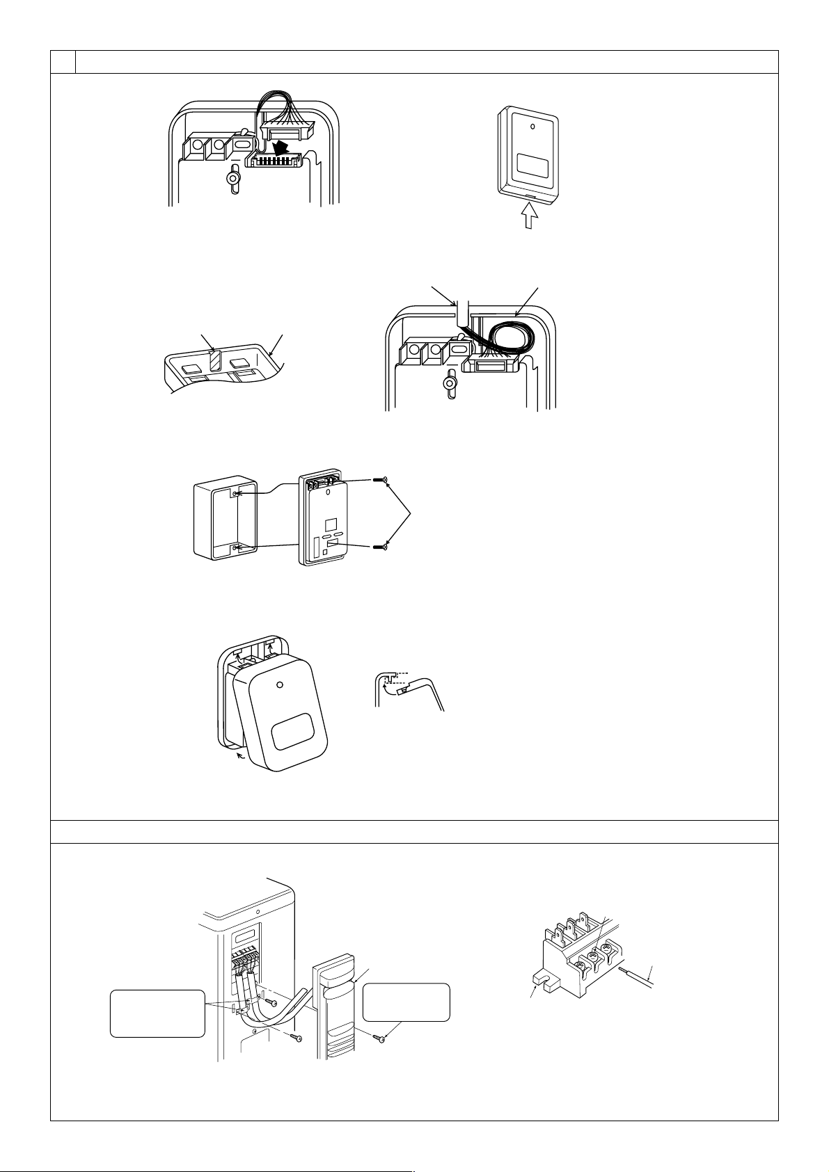
[Fig. 8-16]
[Fig. 8-17]
AB
C
D
A Thin-wall portion
B Bottom case
C Remote controller wire
D Conducting wire
[Fig. 8-18]
A
A Screw (M4 × 30)
* When installing the lower case directly on the wall or the ceiling,
use wood screws.
Insert the minus screwdriver toward the
arrow pointed and wrench it to remove the
cover.
A flat screwdriver whose width of blade is
between 4 and 7 mm (5/32 - 9/32 inch)
must be used.
[Fig. 8-19]
1
1
2
A
1 Hang the cover to the upper hooks (2 places).
2 Mount the cover to the lower case
A Cross-section of upper hooks
A Loosen terminal screw
B Terminal block
C Lead wire
B
C
A
[Fig.8-20] [Fig. 8-21]
Service panel
Remove one fixing
screw to open the
service panel.
Be sure to fix the
indoor/outdoor unit
connecting wire using
this cord clamp.
8.4
KB79H173H01_illust.p65 07.7.9, 2:13 PM7
Loading ...
Loading ...
Loading ...