Loading ...
Loading ...
Loading ...
13
8. Electrical work
5 Signal receiving unit cable (accessory) (wire length : 5 m)
6 Signal receiving unit
7 Power supply cord
Cable 3-core 2.0 mm
2
or more, in conformity with Design 245 IEC 57.
• Connect the terminal blocks as shown in the diagram below.
Caution:
• Use care not to make mis-wiring.
• Firmly tighten the terminal screws to prevent them from loosening.
• After tightening, pull the wires lightly to confirm that they do not move.
8.3. Remote controller
8.3.1. For wireless remote controller
1) Installing procedures
(1) Select an installing position for the remote controller.
The temperature sensors are located on both remote controller and indoor unit.
s Procure the following parts locally:
Two piece switch box
Thin copper conduit tube
Lock nuts and bushings
(2) Seal the service entrance for the remote controller cord with putty to prevent pos-
sible invasion of dew drops, water, cockroaches or worms.
[Fig. 8-4] (P.5)
A For installation in the switch box:
B For direct installation on the wall select one of the following:
• Prepare a hole through the wall to pass the remote controller cord (in order to run the remote
controller cord from the back), then seal the hole with putty.
• Run the remote controller cord through the cut-out upper case, then seal the cut-out notch
with putty similarly as above.
C Wall G Switch box
D Conduit H Remote controller cord
E Lock nut I Seal with putty
F Bushing
B-1. To lead the remote controller cord from the back of the controller:
B-2. To run the remote controller cord through the upper portion:
(3) For direct installation on the wall
8.3.2. Signal Receiving Unit
1) Sample system connection
[Fig. 8-5] (P.5)
Only the wiring from the signal receiving unit and between the remote controllers is
shown in Fig. 8-5. The wiring differs depending on the unit to be connected or the
system to be used.
For details on restrictions, refer to the installation manual or the service handbook
that came with the unit.
1. Connecting to Mr. SLIM air conditioner
(1) Standard 1:1
1 Connecting the signal receiving unit
Connect the signal receiving unit to the CN90 (Connect to the wireless re-
mote controller board) on the indoor unit using the supplied remote controller
wire. Connect the signal receiving units to all the indoor units.
2) Setting the pair number switch
[Fig. 8-6] (P.5)
1. Setting method
Assign the same pair number to the wireless remote controller as that of the indoor
unit. If not doing so, the remote controller cannot be operated. Refer to the instal-
lation manual that came with the wireless remote controller for how to set pair
numbers of wireless remote controllers.
Position of daisy wire on the controller circuit board on the indoor unit.
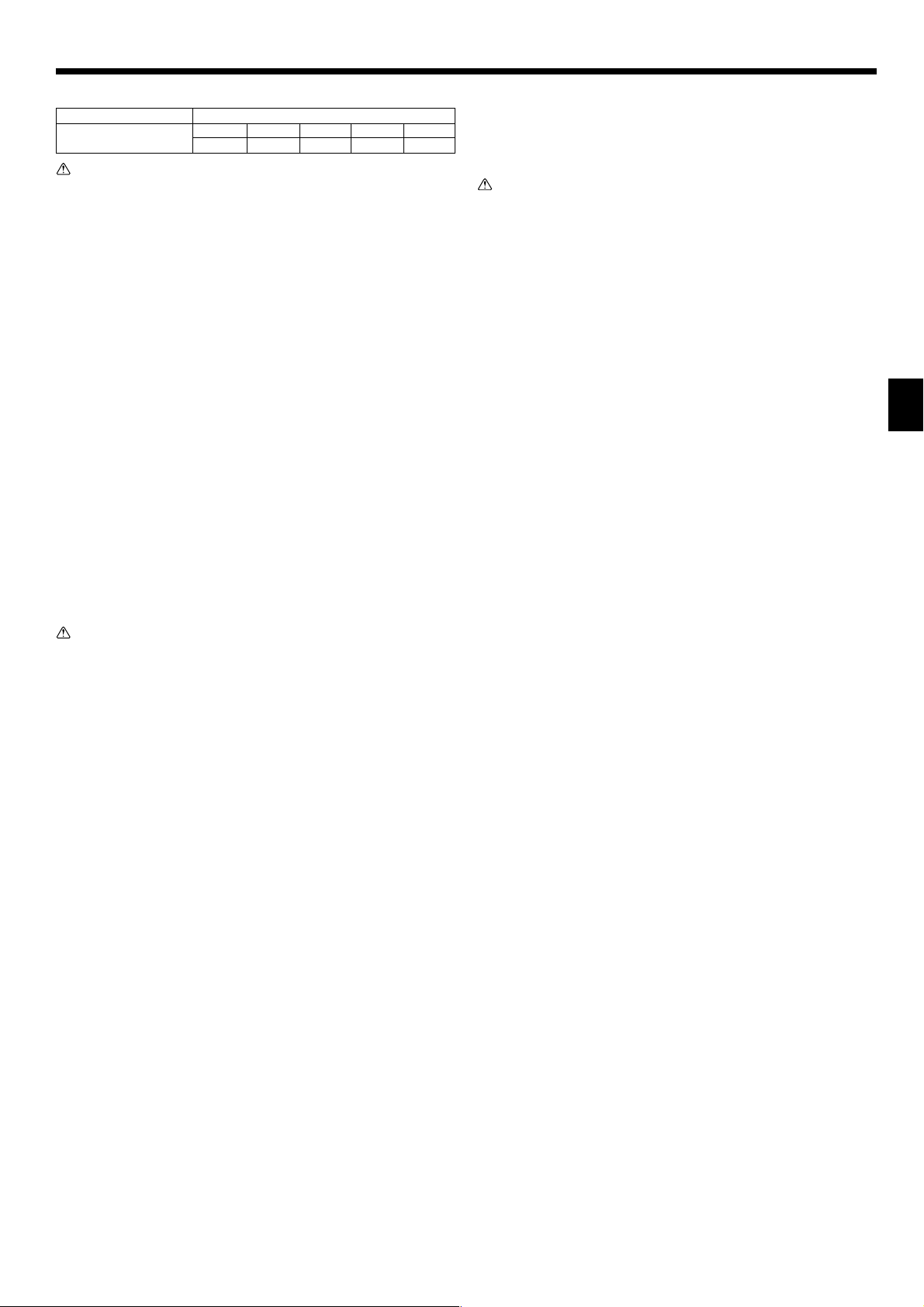
8.1. Power supply
Electrical specification Input capacity Main Switch/Fuse (A)
Power supply
SEZ-KD25 SEZ-KD35 SEZ-KD50 SEZ-KD60 SEZ-KD71
(1 phase ~/N, 230V, 50Hz) 10 10 20 20 20
Warning:
• The compressor will not operate unless the power supply phase connection
is correct.
• Grounding protection with a no-fuse breaker (earth leakage breaker [ELB]) is
usually installed for
DD
DD
D.
• The connection wiring between the outdoor and indoor units can be extended
up to a maximum of 50 meters, and the total extension including the crosso-
ver wiring between rooms is a maximum of 80 m.
A switch with at least 3 mm contact separation in each pole shall be provided
by the air conditioner installation.
* Label each breaker according to purpose (heater, unit etc.).
[Fig. 8-1] (P.4)
A Indoor unit
B Outdoor unit
C Signal receiving unit
D Wireless remote controller
E Main switch/fuse
F Grounding
8.2. Indoor wire connection
Work procedure
1.Remove 2 screws to detach the electric component cover.
2.Route each cable through the wiring intake into the electric component box. (Pro-
cure power cable and in-out connecting cable locally and use remote control cable
supplied with the unit.)
3.Securely connect the power cable and the in-out connecting cable and the remote
control cable to the terminal blocks.
4.Secure the cables with clamps inside the electric component box.
5.Attach the electric component cover as it was.
• Fix power supply cable and indoor/outdoor cable to control box by using buffer
bushing for tensile force. (PG connection or the like.)
Warning:
• Attach the electrical part cover securely. If it is attached incorrectly, it could
result in a fire, electric shock due to dust, water, etc.
• Use the specified indoor/outdoor unit connecting wire to connect the indoor
and outdoor units and fix the wire to the terminal bed securely so that no
stress is applied to the connecting section of the terminal bed. Incomplete
connection or fixing of the wire could result in a fire.
[Fig. 8-2-1] (P.4)
A Screw holding cover (2 pcs)
B Cover
[Fig. 8-2-2] (P.4)
A Terminal bed box
B Knockout hole
C Remove
[Fig. 8-2-3] (P.4)
E Use PG bushing to keep the weight of the cable and external force from being applied to the
power supply terminal connector. Use a cable tie to secure the cable.
F Power source wiring
G Tensile force
H Use ordinary bushing
I Signal receiving unit wiring
[Fig. 8-2-4] (P.4)
J Terminal bed for power source and indoor transmission
K To 1-phase power source
L Connecting the signal receiving unit
Connect the signal receiving unit to the CN90 (Connect to the wireless remote controller
board) on the indoor unit using the supplied remote controller wire. Connect the signal re-
ceiving units to all the indoor units.
• Perform wiring as shown in the diagram to the lower left. (Procure the cable locally.)
Make sure to use cables of the correct polarity only.
[Fig. 8-3] (P.5)
A Indoor terminal block
B Earth wire (green/yellow)
C Indoor/outdoor unit connecting wire 3-core 1.5 mm
2
or more
D Outdoor terminal block
E Power supply cord : 2.0 mm
2
or more
F Indoor controller board
1 Connecting cable
Cable 3-core 1.5 mm
2
, in conformity with Design 245 IEC 57.
2 Indoor terminal block
3 Outdoor terminal block
4 Always install an earth wire (1-core 1.5 mm
2
) longer than other cables
KB79H173H01_en.p65 07.7.9, 5:13 PM13
Loading ...
Loading ...
Loading ...