Loading ...
Loading ...
Loading ...
11
6. Refrigerant piping work
6.1. Refrigerant pipe
[Fig. 6-1] (P.3)
a Indoor unit
b Outdoor unit
Refer to the Instruction Manual that came with the outdoor unit for the restrictions on
the height difference between units and for the amount of additional refrigerant
charge.
Avoid the following places for installation where air conditioner trouble is liable to
occur.
• Where there is too much oil such as for machine or cooking.
• Salty environment as seaside areas.
• Hot-spring areas.
• Where sulfide gas exists.
• Other special atmospheric areas.
• This unit has flared connections on both indoor and outdoor sides. (Fig. 6-1)
• Refrigerant pipes are used to connect the indoor and outdoor units as shown in the
figure below.
• Insulate both refrigerant and drainage piping completely to prevent condensation.
Piping preparation
• Refrigerant pipes of 3, 5, 7, 10 and 15 m are available as optional items.
(1) Table below shows the specifications of pipes commercially available.
(2) Ensure that the 2 refrigerant pipes are well insulated to prevent condensation.
(3) Refrigerant pipe bending radius must be 10 cm or more.
Caution:
Using careful insulation of specified thickness. Excessive thickness prevents
storage behind the indoor unit and smaller thickness causes dew drippage.
6.2. Flaring work
• Main cause of gas leakage is defect in flaring work.
Carry out correct flaring work in the following procedure.
6.2.1. Pipe cutting
[Fig. 6-3] (P.3)
a Copper tubes
b Good
c No good
d Tilted
e Uneven
f Burred
• Using a pipe cutter cut the copper tube correctly.
6.2.2. Burrs removal
[Fig. 6-4] (P.3)
a Burr
b Copper tube/pipe
c Spare reamer
d Pipe cutter
• Completely remove all burrs from the cut cross section of pipe/tube.
• Put the end of the copper tube/pipe to downward direction as you remove burrs in
order to avoid burrs drop in the tubing.
6.2.3. Putting nut on
[Fig. 6-5] (P.3)
a Flare nut
b Copper tube
• Remove flare nuts attached to indoor and outdoor unit, then put them on pipe/tube
having completed burr removal.
(not possible to put them on after flaring work)
6.2.4. Flaring work
[Fig. 6-6] (P.3)
a Flaring tool
b Die
c Copper tube
d Flare nut
e Yo k e
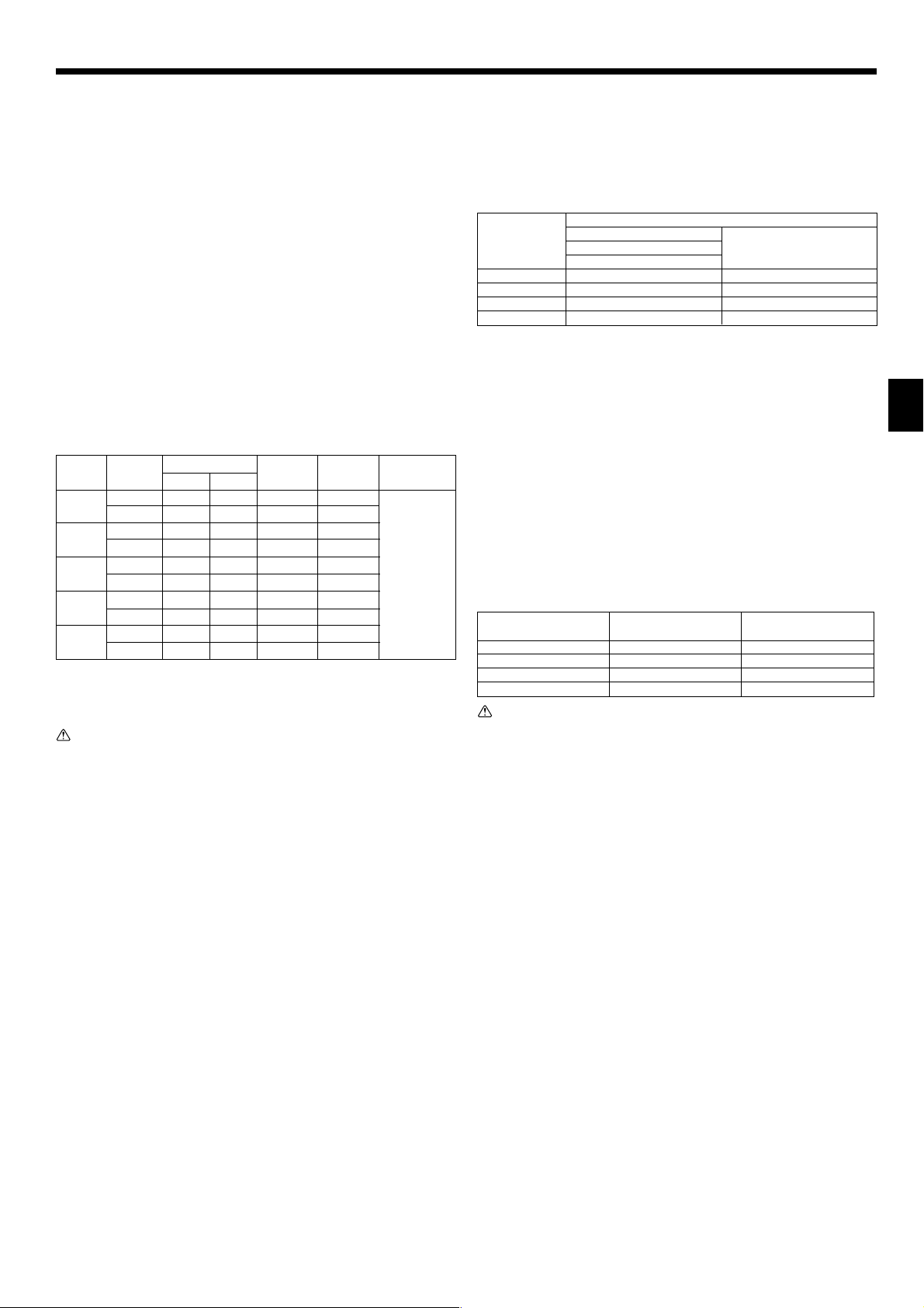
• Carry out flaring work using flaring tool as shown below.
Dimension
Pipe diameter A (mm)
(mm)
When the tool for R410A is used
B (mm)
Clutch type
6.35 0 - 0.5 9.1
9.52 0 - 0.5 13.2
12.7 0 - 0.5 16.6
15.88 0 - 0.5 19.7
Firmly hold copper tube in a die in the dimension shown in the table at above.
6.2.5. Check
[Fig. 6-7] (P.3)
a Smooth all around f Scratch on flared plane
b Inside is shining without any scratches g Cracked
c Even length all around h Uneven
d Too much i Bad examples
e Tilted
• Compare the flared work with a figure in right side hand.
• If flare is noted to be defective, cut off the flared section and do flaring work again.
6.3. Pipe connection
[Fig. 6-8] (P.3)
• Apply a thin coat of refrigeration oil on the seat surface of pipe.
• For connection first align the center, then tighten the first 3 to 4 turns of flare nut.
• Use tightening torque table below as a guideline for indoor unit side union joint section,
and tighten using two wrenches. Excessive tightening damages the flare section.
Copper pipe O.D. Flare nut O.D. Tightening torque
(mm) (mm) (N·m)
ø6.35 17 14 - 18
ø9.52 22 34 - 42
ø12.7 26 49 - 61
ø15.88 29 68 - 82
Warning:
Be careful of flying flare nut! (Internally pressurized)
Remove the flare nut as follows:
1. Loosen the nut until you hear a hissing noise.
2. Do not remove the nut until the gas has been completely released (i.e., hiss-
ing noise stops).
3. Check that the gas has been completely released, and then remove the nut.
Outdoor unit connection
Connect pipes to stop valve pipe joint of the outdoor unit in the same manner applied
for indoor unit.
• For tightening use a torque wrench or spanner, and use the same tightening torque
applied for indoor unit.
Refrigerant pipe insulation
• After connecting refrigerant piping, insulate the joints (flared joints) with thermal
insulation tubing as shown below.
[Fig. 6-9] (P.3)
A Pipe cover (small) (accessory)
B Caution:
Pull out the thermal insulation on the refrigerant piping at the site, insert the flare nut to flare
the end, and replace the insulation in its original position.
Take care to ensure that condensation does not form on exposed copper piping.
C Liquid end of refrigerant piping D Gas end of refrigerant piping
E Site refrigerant piping F Main body
G Pipe cover (large) (accessory) H Thermal insulation (field supply)
I Pull J Flare nut
K Return to original position L Ensure that there is no gap here
M Plate on main body N Band (accessory)
O Ensure that there is no gap here. Place join upwards.
Outside diameter
mm inch
6.35 1/4
9.52 3/8
6.35 1/4
9.52 3/8
6.35 1/4
12.7 1/2
6.35 1/4
15.88 5/8
9.52 3/8
15.88 5/8
+0
-0.4
Pipe
For liquid
For gas
For liquid
For gas
For liquid
For gas
For liquid
For gas
For liquid
For gas
Model
SEZ-
KD25
SEZ-
KD35
SEZ-
KD50
SEZ-
KD60
SEZ-
KD71
Insulation
material
Heat resisting
foam plastic
0.045 specific
gravity
Insulation
thickness
8 mm
8 mm
8 mm
8 mm
8 mm
8 mm
8 mm
8 mm
8 mm
8 mm
Min wall
thickness
0.8 mm
0.8 mm
0.8 mm
0.8 mm
0.8 mm
0.8 mm
0.8 mm
1.0 mm
0.8 mm
1.0 mm
KB79H173H01_en.p65 07.7.9, 5:13 PM11
Loading ...
Loading ...
Loading ...