Loading ...
Loading ...
Loading ...
4
E
F
I
H
G
S3
S2
S1
S3
S2S1
CN90
L
J
K
A
B
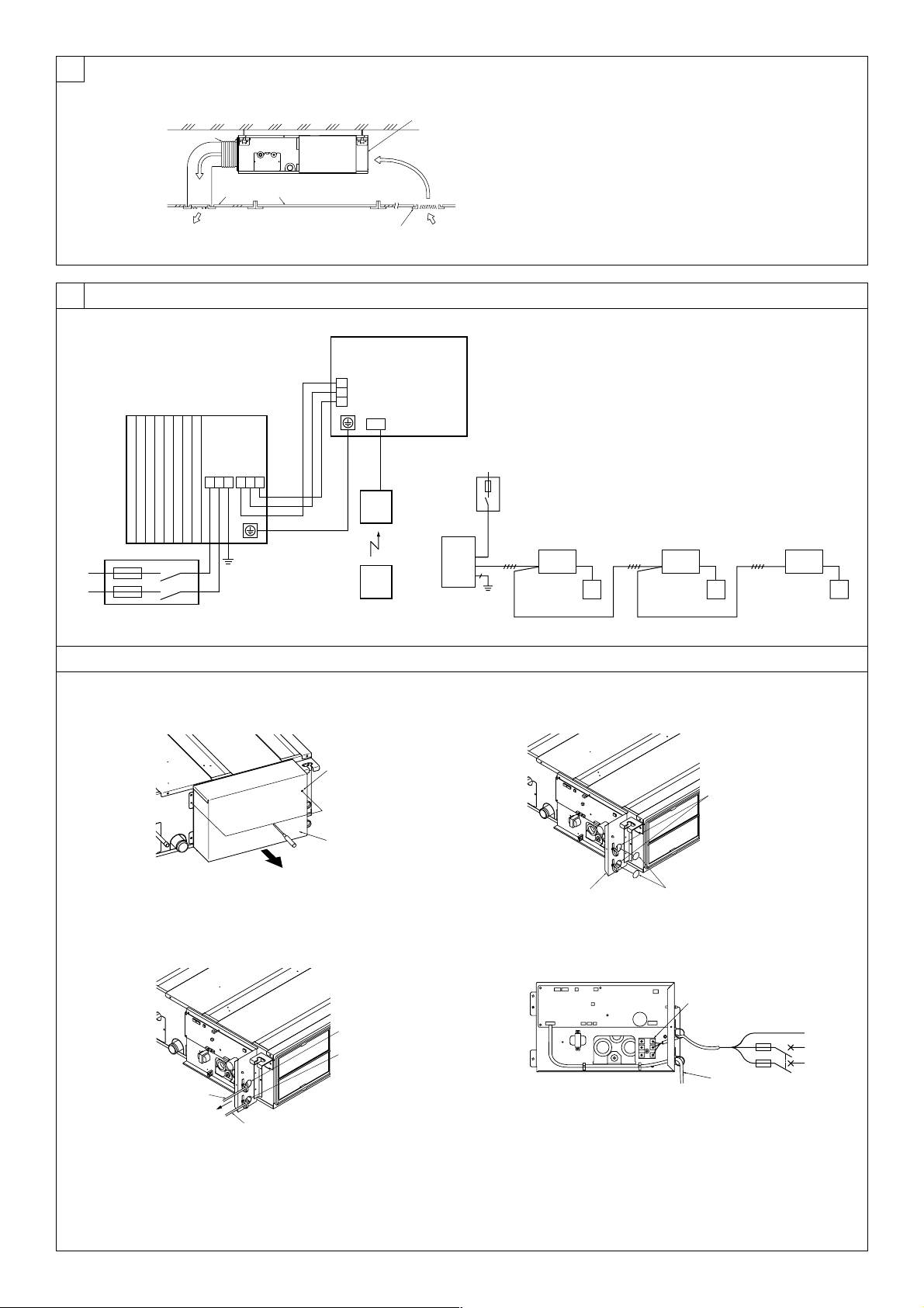
A Indoor unit
B Outdoor unit
C Signal receiving unit
D Wireless remote controller
E Main switch/fuse
F Grounding
[Fig. 8-1]
[Fig. 8-2-1]
A
C
D
B
E
S3
S3
S2
S1
S2S1
For Power supply
For Power
supply
E Use PG bushing to keep the weight of the cable and external force from being
applied to the power supply terminal connector. Use a cable tie to secure the cable.
F Power source wiring
G Tensile force
H Use ordinary bushing
I Signal receiving unit wiring
J Terminal bed for power source and indoor transmission
K To 1-phase power source
L Connecting the signal receiving unit
Connect the signal receiving unit to the CN90 (Connect to the wireless remote
controller board) on the indoor unit using the supplied remote controller wire. Con-
nect the signal receiving units to all the indoor units.
A Terminal bed box
B Knockout hole
C Remove
A Screw holding cover (2pcs)
B Cover
[Fig. 8-2-3] [Fig. 8-2-4]
[Fig. 8-2-2]
F
G
E
DC
BA
[Fig. 7-1]
A Air inlet
B Air outlet
C Access door
D Ceiling surface
E Canvas duct
F Air filter
G Inlet grille
7
E
F
C C
B
A A
C
A
8.2
A
B
C
8
8.1
KB79H173H01_illust.p65 07.7.9, 2:13 PM4
Loading ...
Loading ...
Loading ...