Loading ...
Loading ...
Loading ...
6
8
8.3
A
B
C
D
E
G
H
F
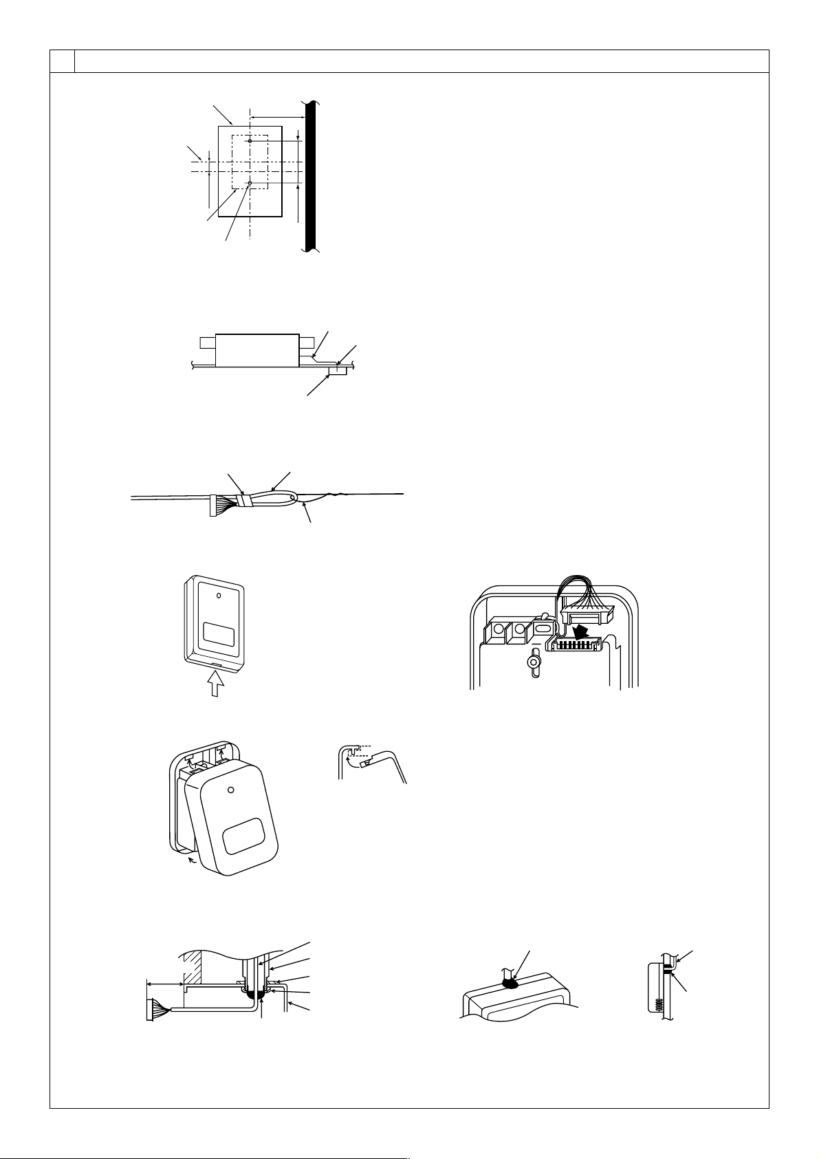
A Signal receiving unit external
B Center of Switch box
C Switch box
D Installation pitch
E 6.5 mm (1/4 inch)
F 70 mm (2 - 3/4 inch)
G 83.5 ± 0.4 mm (3 - 9/32 inch)
H Protrusion (pillar, etc)
[Fig. 8-11]
A
B
C
A Remote controller wire
B Hole (drill a hole on the ceiling to pass the remote controller wire.)
C Signal Receiving Unit
Ceiling cassette type, Ceiling concealed type
[Fig. 8-12]
A
B
C
A Fix tightly with tape.
B Remote controller wire
C Order wire
[Fig. 8-13]
A
Insert the minus screwdriver toward the
arrow pointed and wrench it to remove
the cover.
A flat screwdriver whose width of blade is
between 4 and 7 mm (5/32 - 9/32 inch)
must be used.
[Fig. 8-14]
1
1
2
A
Indoor unit
1 Hang the cover to the upper hooks (2 places).
2 Mount the cover to the lower case
A Cross-section of upper hooks
[Fig. 8-10]
[Fig. 8-15]
H
J
I
When using the switch box
When installing directly on the wall
A 150 mm (5 - 15/16 inch)
B Remote controller wire (Accessory)
C Wiring pipe
D Locknut
H Seal around here with putty
I Remote controller wire
J Seal around here with putty
E Bushing
F Switch box
G Seal around here with putty
C
D
B
F
E
G
A
Wall
KB79H173H01_illust.p65 07.7.9, 2:13 PM6
Loading ...
Loading ...
Loading ...