Loading ...
Loading ...
3
6
[Fig. 6-1]
ØB
ØA
a
b
a Indoor unit
b Outdoor unit
a
d
cb
ef
90°
d
c
b
a
b
a
a
b
e
b
c
d
c
A
c
b
a
defgh
i
[Fig. 6-9]
A
B
C
D
F
G
E
M
L
E
F
L
AG
H
H
K
L
J
I
J
O
O
N
N
20
20
20
20
A
B 1
[Fig. 6-10]
[Fig. 6-3]
[Fig. 6-6]
[Fig. 6-4] [Fig. 6-5]
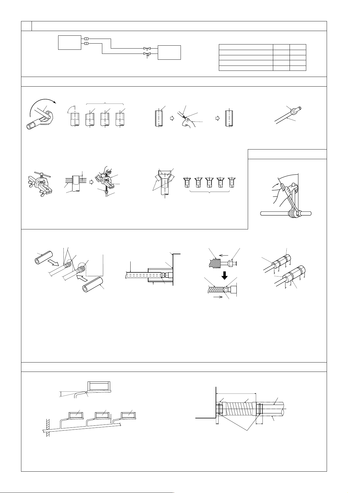
a Flare nut
b Copper tube
a Burr
b Copper tube/pipe
c Spare reamer
d Pipe cutter
[Fig. 6-7]
[Fig. 6-8]
C C C
D 2
E
A Downward slope 1/100 or more
B Connection dia. R1 external thread
C Indoor unit
D Collective piping
E Maximize this length to approx. 10 cm
a Flaring tool
b Die
c Copper tube
d Flare nut
e Yo k e
a Smooth all around
b Inside is shining without
any scratches
c Even length all around
d Too much
e Tilted
f Scratch on
flared plane
g Cracked
h Uneven
i Bad examples
6.1
6.2
a Copper tubes
b Good
c No good
d Tilted
e Uneven
f Burred
6.3
6.5
Model
SEZ-KD25, 35
SEZ-KD50
SEZ-KD60
SEZ-KD71
A
9.52
12.7
15.88
15.88
B
6.35
6.35
6.35
9.52
D
E
H
G
I
F
B
C
525
A
A Indoor unit
B Pipe cover (short) (accessory)
C Tie band (accessory)
D Band fixing part
E Insertion margin
F Drain hose (accessory)
G Drain pipe (O.D. ø32 PVC TUBE, field supply)
H Insulating material (field supply)
I Max.145 ± 5 mm
[Fig. 6-11]
A Pipe cover (small) (accessory)
B Caution:
Pull out the thermal insulation on the refrigerant piping at the
site, insert the flare nut to flare the end, and replace the insu-
lation in its original position.
Take care to ensure that condensation does not form on ex-
posed copper piping.
C Liquid end of refrigerant piping
D Gas end of refrigerant piping
E Site refrigerant piping
F Main body
G Pipe cover (large) (accessory)
H Thermal insulation (field supply)
I Pull
J Flare nut
K Return to original position
L Ensure that there is no gap here
M Plate on main body
N Band (accessory)
O Ensure that there is no gap here. Place join upwards.
KB79H173H01_illust.p65 07.7.9, 2:12 PM3
Loading ...
Loading ...
Loading ...