Loading ...
Loading ...
Loading ...
15
8. Electrical work
8.5. Function settings
8.5.1 Function setting on the unit (Selecting the unit functions)
1) AUTO RESTART FUNCTION
For wireless remote controller only [Fig. 8-22] (P.8)
This model is equipped with the AUTO RESTART FUNCTION.
When the indoor unit is controlled with the remote controller, the operation mode, set
temperature, and the fan speed are memorized by the indoor controller board. The
auto restart function sets to work the moment the power has restored after power
failure, then, the unit will restart automatically.
8.5.2. Function setting on the unit (Selecting the unit functions)
[Fig. 8-22] (P.8)
Changing the power voltage setting
• Be sure to change the power voltage setting depending on the voltage used.
1 Go to the function select mode
Press the CHECK button F twice continuously.
(Start this operation from the status of remote controller display turned off.)
CHECK
is lighted and “00” blinks.
Press the TEMP button C once to set “50”. Direct the wireless remote controller
toward the receiver of the indoor unit and press the Hour button A.
2 Setting the unit number
Press the TEMP button C and D to set the unit number “00”. Direct the wireless
remote controller toward the receiver of the indoor unit and press the Minute
button B.
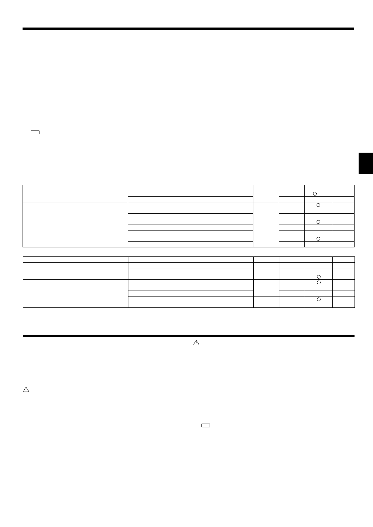
Function table
Select unit number 00
Settings
Not available
Available
Indoor unit operating average
Set by indoor unit’s remote controller
Remote controller’s internal sensor
Not Supported
Supported (indoor unit is not equipped with outdoor-air intake)
Supported (indoor unit is equipped with outdoor-air intake)
Energy saving cycle automatically enabled
Energy saving cycle automatically disabled
Mode no. Setting no. Initial setting Setting
1 (*1)
01
2
1
02 2
3
1
03 2
3
1
05
2
Mode
Power failure automatic recovery*1
(AUTO RESTART FUNCTION)
Indoor temperature detecting
LOSSNAY connectivity
Auto mode
Select unit numbers 01 to 03 or all units (AL [wired remote controller]/07 [wireless remote controller])
*1 When the power supply returns, the air conditioner will start 3 minutes later.
Mode
Filter sign
External static pressure
Settings
100 Hr
2500 Hr
No filter sign indicator
15 Pa
35 Pa
50 Pa
The same as setting of mode no.08
5 Pa (set mode no. 08 to 1)
Mode no. Setting no. Initial setting Setting
1
07 2
3
1
08 2
3
1
10
2
9.1. Before test run
s After completing installation and the wiring and piping of the indoor and outdoor
units, check for refrigerant leakage, looseness in the power supply or control
wiring, wrong polarity, and no disconnection of one phase in the supply.
s Use a 500-volt megohmmeter to check that the resistance between the power
supply terminals and ground is at least 1.0 MΩ.
s Do not carry out this test on the control wiring (low voltage circuit) termi-
nals.
Warning:
Do not use the air conditioner if the insulation resistance is less than 1.0 MΩ.
Insulation resistance
After installation or after the power source to the unit has been cut for an extended
period, the insulation resistance will drop below 1 MΩ due to refrigerant accumulat-
ing in the compressor. This is not a malfunction. Perform the following procedures.
1. Remove the wires from the compressor and measure the insulation resistance of
the compressor.
2. If the insulation resistance is below 1 MΩ, the compressor is faulty or the resist-
ance dropped due the accumulation of refrigerant in the compressor.
3. After connecting the wires to the compressor, the compressor will start to warm
up after power is supplied. After supplying power for the times indicated below,
measure the insulation resistance again.
• The insulation resistance drops due to accumulation of refrigerant in the com-
pressor. The resistance will rise above 1 MΩ after the compressor is warmed
up for two to three hours.
(The time necessary to warm up the compressor varies according to atmos-
pheric conditions and refrigerant accumulation.)
• To operate the compressor with refrigerant accumulated in the compressor,
the compressor must be warmed up at least 12 hours to prevent breakdown.
4. If the insulation resistance rises above 1 MΩ, the compressor is not faulty.
9. Test run
Caution:
• The compressor will not operate unless the power supply phase connection
is correct.
• Turn on the power at least 12 hours before starting operation.
- Starting operation immediately after turning on the main power switch can result in
severe damage to internal parts. Keep the power switch turned on during the op-
erational season.
9.2. Test run
9.2.1. Using wireless remote controller
[Fig. 9-1] (P.8)
1 Turn on the power to the unit at least 12 hours before the test run.
2 Press the TEST RUN button A twice continuously.
(Start this operation from the status of remote controller display turned off.)
TEST RUN
and current operation mode are displayed.
3 Press the MODE button B to activate COOL mode, then check whether cool air
is blown out from the unit.
4 Press the MODE button B to activate HEAT mode, then check whether warm air
is blown out from the unit.
5 Press the FAN button C and check whether fan speed changes.
6 Press the VANE button D and check whether the auto vane operates properly.
7 Press the ON/OFF button to stop the test run.
Note:
• Point the remote controller towards the indoor unit receiver while following
steps
22
22
2 to
77
77
7.
• It is not possible to run the in FAN, DRY or AUTO mode.
3 Selecting a mode
Enter 04 to change the power voltage setting using the C and D buttons.
Direct the wireless remote controller toward the receiver of the indoor unit and
press the Hour button A.
Current setting number: 1 = 1 beep (one second)
2 = 2 beeps (one second each)
3 = 3 beeps (one second each)
4 Selecting the setting number
Use the C and D buttons to change the power voltage setting to 01 (240 V).
Direct the wireless remote controller toward the sensor of the indoor unit and
press the Hour button A.
5 To select multiple functions continuously
Repeat steps 3 and 4 to change multiple function settings continuously.
6 Complete function selection
Direct the wireless remote controller toward the sensor of the indoor unit and
press the ON/OFF button E.
Note:
• Whenever changes are made to the function settings after installation or main-
tenance, be sure to record the changes with a mark in the “Setting” column of
the Function table.
8.5.3 Function setting on the remote controller
Refer to the indoor unit operation manual.
KB79H173H01_en.p65 07.7.9, 5:13 PM15
Loading ...
Loading ...
Loading ...