Loading ...
Loading ...
Loading ...
5
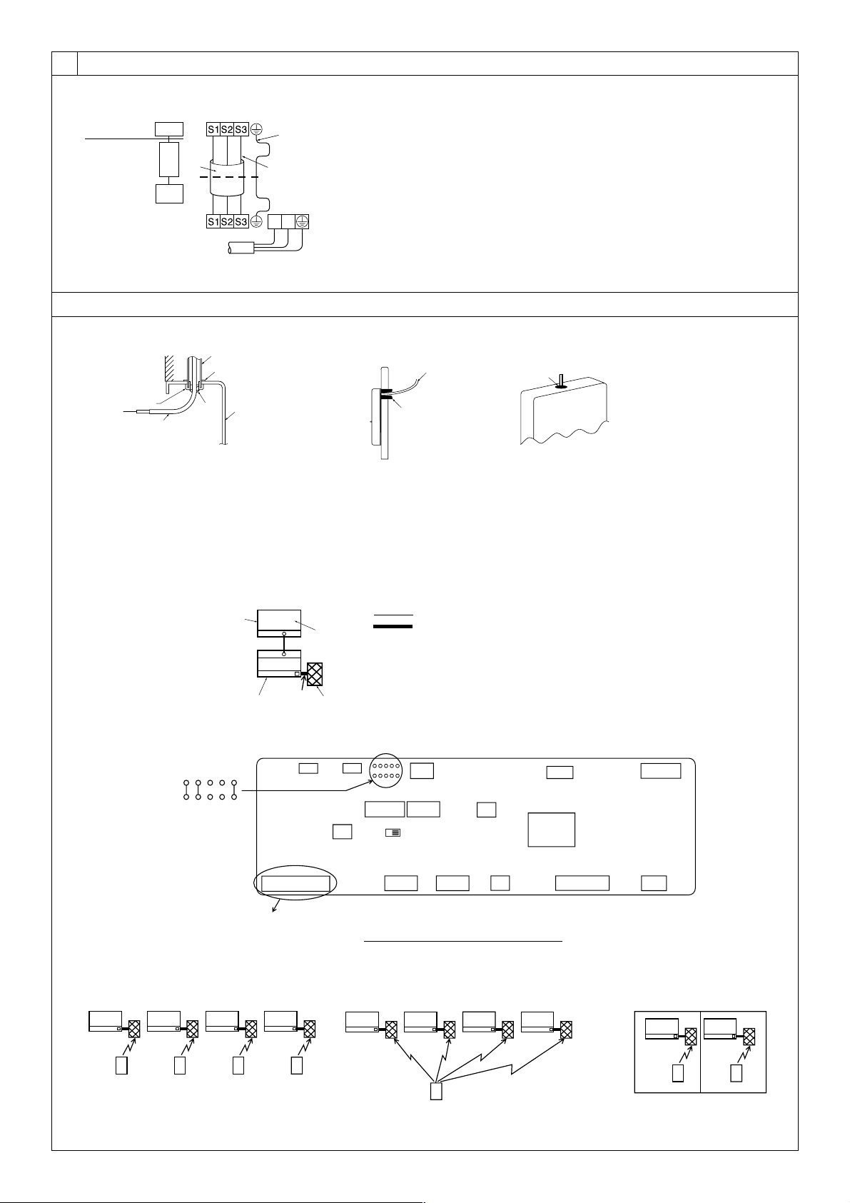
A For installation in the switch box:
B For direct installation on the wall select one of the following:
• Prepare a hole through the wall to pass the remote controller cord (in order to run the remote controller cord from
the back), then seal the hole with putty.
• Run the remote controller cord through the cut-out upper case, then seal the cut-out notch with putty similarly as
above.
C Wall
D Conduit
E Lock nut
F Bushing
G Switch box
H Remote controller cord
I Seal with putty
F
A
H
C
D
E
G
I
I
I
H
B
B-1. B-2.
[Fig. 8-4]
8.3
[Fig. 8-3]
A Indoor terminal block
B Earth wire (green/yellow)
C Indoor/outdoor unit connecting wire 3-
core 1.5 mm
2
or more
D Outdoor terminal block
E Power supply cord : 2.0 mm
2
or more
F Indoor controller board
1 Connecting cable
Cable 3-core 1.5 mm
2
, in conformity
with Design 245 IEC 57.
2 Indoor terminal block
CN90
6
5
2
4
3
7
L
N
1
A Indoor terminal block
C Indoor/outdoor unit
connecting wire
3-core 1.5 mm
2
or
more
D Outdoor terminal block
B Earth wire (green/yellow)
E Power supply cord : 2.0 mm
2
or more
3 Outdoor terminal block
4 Always install an earth wire (1-core 1.5
mm
2
) longer than other cables
5 Signal receiving unit cable (accessory)
(wire length : 5 m)
6 Signal receiving unit
7 Power supply cord
Cable 3-core 2.0 mm
2
or more, in con-
formity with Design 245 IEC 57.
F Indoor controller
board
8
8.2
J41
J42
JP1
JP2
JP3
CN90 CN4F CN44 CN20(Red) CNMF
SW1 SW2
CN32
CN41CN51
ON OFF
SWE
CN2L
CN22(Blue)
CNP
(Blue)
CN3C(Blue)
CN01
(Black)
CN90: Connector for remote controller wire connection
Controller circuit board on the indoor unit (reference)
IC
OC(00)
CN90
TB1
TB4
1
D
C
A
B
Standard 1:1
[Fig. 8-5]
[Fig. 8-6]
IC IC IC IC
CN90 CN90 CN90 CN90
Pair number: 0
[Fig. 8-7]
IC
CN90
IC
CN90
IC IC IC IC
CN90 CN90 CN90 CN90
[Fig. 8-9][Fig. 8-8]
Pair number: 0 Pair number: 1 Pair number: 2 Pair number: 3
Pair number: 0 Pair number: 1 Pair number: 2 Pair number: 3
Pair number: 0 Pair number: 0 Pair number: 0 Pair number: 0
Pair number: 0 Pair number: 0
Pair number: 0
A Outdoor unit
B Refrigerant address
C Indoor unit
D Signal receiving unit
Indoor/outdoor wiring
Signal receiving unit wiring
KB79H173H01_illust.p65 07.7.9, 2:13 PM5
Loading ...
Loading ...
Loading ...