Loading ...
Loading ...
Loading ...
10
3. Selecting an installation site & Accessories
• Select a site with sturdy fixed surface sufficiently durable against the weight of unit.
• Before installing unit, the routing to carry in unit to the installation site should be
determined.
• Select a site where the unit is not affected by entering air.
• Select a site where the flow of supply and return air is not blocked.
• Select a site where refrigerant piping can easily be led to the outside.
• Select a site which allows the supply air to be distributed fully in room.
• Do not install unit at a site with oil splashing or steam in much quantity.
• Do not install unit at a site where combustible gas may generate, flow in, stagnate
or leak.
• Do not install unit at a site where equipment generating high frequency waves (a
high frequency wave welder for example) is provided.
• Do not install unit at a site where fire detector is located at the supply air side. (Fire
detector may operate erroneously due to the heated air supplied during heating
operation.)
• When special chemical product may scatter around such as site chemical plants
and hospitals, full investigation is required before installing unit. (The plastic com-
ponents may be damaged depending on the chemical product applied.)
• If the unit is run for long hours when the air above the ceiling is at high temperature/
high humidity (due point above 26 °C), due condensation may be produced in the
indoor unit. When operating the units in this condition, add insulation material (10-
20 mm) to the entire surface of the indoor unit to avoid due condensation.
3.1. Install the indoor unit on a ceiling strong enough
to sustain its weight
[Fig. 3-1] (P.2)
A Access door B Electrical parts box
C Air inlet D Air outlet
E Ceiling surface
F Service space (viewed from the side)
G Service space (viewed from the direction of arrow)
1 600 mm or more 2 100 mm or more
3 10 mm or more 4 300 mm or more
* If the optional long-life filter is installed, the dimensions of the air conditioner
increase.
Rear inlet: Depth increases by 30 mm (*1)
Bottom inlet: Height increases by 30 mm (*2)
Warning:
The unit must be securely installed on a structure that can sustain its weight. If
the unit is mounted on an unstable structure, it may fall down causing injuries.
3.2. Securing installation and service space
• Select the optimum direction of supply airflow according to the configuration of the
room and the installation position.
• As the piping and wiring are connected at the bottom and side surfaces, and the
maintenance is made at the same surfaces, allow a proper space properly. For the
efficient suspension work and safety, provide a space as much as possible.
3.3. Outdoor unit
Ventilation and service space
■ SUZ-KA25VA
[Fig. 3-2] (P.2)
A 100 mm or more
B 350 mm or more
C Basically open 100 mm or more without only obstruction in front and on both sides of the
unit.
D 200 mm or more (Open two sides of left, right, or rear side.)
When the piping is to be attached to a wall containing metals (tin plated) or metal
netting, use a chemically treated wooden piece 20 mm or thicker between the wall
and the piping or wrap 7 to 8 turns of insulation vinyl tape around the piping.
Units should be installed by licensed contractor accordingly to local code require-
ment.
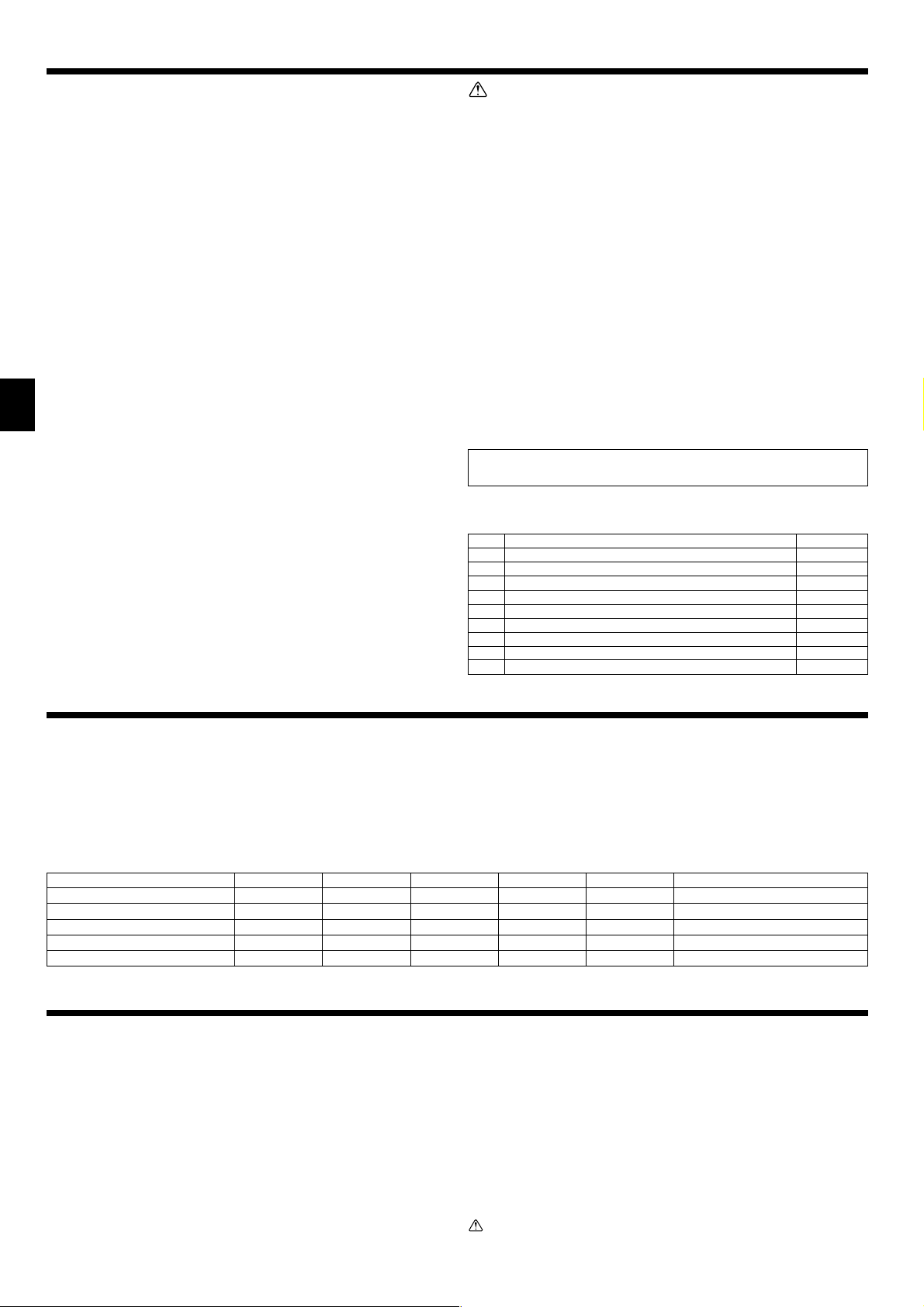
3.4. Indoor unit accessories
The unit is provided with the following accessories:
No. Name Quantity
1 Pipe cover (for refrigerant piping joint) Small diameter 1
2 Pipe cover (for refrigerant piping joint) Large diameter 1
3
Bands for temporary tightening of pipe cover and drain hose
6
4 Remote controller parts 1
5 Signal receiving unit 1
6 Signal receiving unit cable 1
7 Washer 8
8 Drain hose 1
9 Pipe cover (for Drain hose) short 1
4. Fixing hanging bolts
4.1. Fixing hanging bolts
[Fig. 4-1] (P.2)
A Center of gravity
(Give site of suspension strong structure.)
Hanging structure
• Ceiling: The ceiling structure varies from building to one another. For detailed infor-
mation, consult your construction company.
• If necessary, reinforce the hanging bolts with anti-quake supporting members as
countermeasures against earthquakes.
* Use M10 for hanging bolts and anti-quake supporting members (field supply).
1 Reinforcing the ceiling with additional members (edge beam, etc.) must be re-
quired to keep the ceiling at level and to prevent the ceiling from vibrations.
2 Cut and remove the ceiling members.
3 Reinforce the ceiling members, and add other members for fixing the ceiling boards.
5. Installing the unit
5.1. Hanging the unit body
ss
ss
s Bring the indoor unit to an installation site as it is packed.
ss
ss
s To hang the indoor unit, use a lifting machine to lift and pass through the
hanging bolts.
[Fig. 5-1] (P.2)
A Unit body
B Lifting machine
[Fig. 5-2] (P.2)
C Nuts (field supply)
D Washers (accessory)
E M10 hanging bolt (field supply)
5.2. Confirming the unit’s position and fixing hanging
bolts
ss
ss
s Use the gage supplied with the panel to confirm that the unit body and
hanging bolts are positioned in place. If they are not positioned in place, it
may result in dew drops due to wind leak. Be sure to check the positional
relationship.
ss
ss
s Use a level to check that the surface indicated by
AA
AA
A is at level. Ensure that
the hanging bolt nuts are tightened to fix the hanging bolts.
ss
ss
s To ensure that drain is discharged, be sure to hang the unit at level using a
level.
[Fig. 5-3] (P.2)
A Indoor unit’s bottom surface
Caution:
Be sure to install the unit body at level.
Center of gravity and Product Weight
Model name
SEZ-KD25
SEZ-KD35
SEZ-KD50
SEZ-KD60
SEZ-KD71
W
625
625
625
625
625
L
752
952
952
1152
1152
X
263
286
280
285
285
Y
351
448
437
527
527
Z
106
104
104
104
104
Product Weight (kg)
18
21
24
28
28
KB79H173H01_en.p65 07.7.9, 5:13 PM10
Loading ...
Loading ...
Loading ...