Loading ...
Loading ...
Loading ...
39FREESTANDING INSTALLATION38 SLOT-IN INSTALLATION
Slot-in Installation
INSTALLATION OF THE APPLIANCE
To remove the appliance kick panel
• Remove all loose parts i.e. Burner crowns and caps,
trivets, oven shelves.
• Carefully lay down the appliance onto one side
onto foam packaging and remove the screws as
shown from each corner bracket.
Remove 4 screws on
each corner bracket
Slot in conversion
To convert the free standing appliance to a slot in
installation the kick panel provided on the appliance
is removed and the appliance is mounted on a plinth.
This enables a continuous cupboard kick board to be
installed, giving a more integrated appearance. There is no
clearance requirement between oven and adjacent side
cabinets.
Remove 4 screws on
each corner bracket
600mm minimum
vertical clearance
from combustible
surfaces
600mm
755mm NOM
900mm minimum
This surface is to be level
with the top edge of the
kickboard
INSTALLATION OF THE APPLIANCE
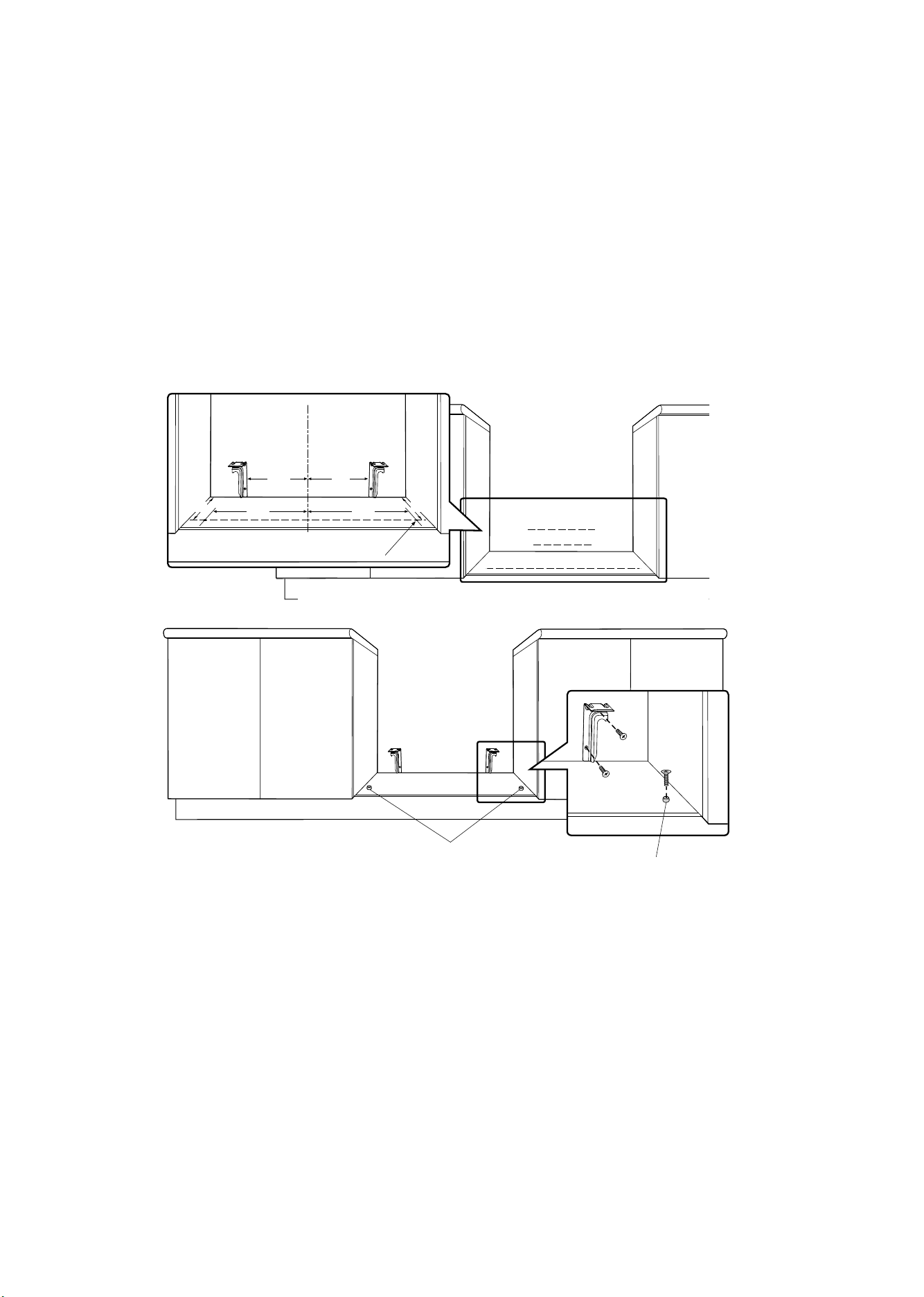
Installation of anti-tilt brackets and stops
• The brackets are to be secured to the back wall
with appropriate fasteners.
• The bottom edge of the the brackets rest on the
horizontal support surface.
• Two stops are to be screwed to the plinth in
locations as shown (stops provided). The stops
locate into slots in the base of the appliance to
prevent the product from being pulled forward
when installed.
• Measurements from the rear wall are to be adjusted
if there are tiles etc. that come between the
appliance and the wall.
• Once services are connected, product can be lifted
onto the plinth and pushed back carefully, ensuring
the appliance engages into both brackets at the
rear and the front stops.
• If the product requires removal for service, it must
be lifted at the front approximately 5mm to clear
the front stops prior to being pulled forward.
Installation sequence for freestanding
or slot in installation
• Check that the required services are correctly
positioned (see electrical & gas services
requirements).
• Ensure cabinetry has the correct details.
• Install anti-tilt brackets and chain hook or front
stops as appropriate.
• Remove all packaging from cooker, remove all loose
parts i.e. Trivets, burner crowns, oven shelves.
• Remove plastic film from cooker.
• Fit splashback to cooker.
• Slide cooker into position to check fitment to anti-
tilt bracket. For freestanding installation, check the
height and level of the cooker. Adjust cooker feet as
required.
• Connect gas and electrical services.
• Place into position.
• Complete Certificate of Compliance.
+
+
+
+
+
+
C
L
183
183
414414
475 475
Location of holes for front stops
Measurements are to be adjusted to account for the thickness of any skirting
board or tiles coming between the back of the appliance and the wall
Front stops
Front stops
Loading ...
Loading ...
Loading ...