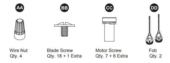
1. Turn off circuit breakers and wall switch to the fan supply line leads
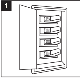
2a. Choose the desired mounting method:
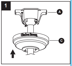
A. Standard Mounting: Standard mounting is best suited for ceilings 8 ft. or higher. For taller ceilings you may want to use a longer downrod (not included)
B. Angle Mounting: Angle-style mounting is best suited for angled or vaulted ceilings. A longer downrod is sometimes necessary to ensure proper blade clearance. If using the angle mount, make sure the ceiling angle is not steeper than 20°.
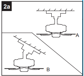
2b. It is required at least 30 inch from blade tip to nearest wall or obstruction. Check downrod length to ensure 7 feet from bottom edge of blade to the floor.
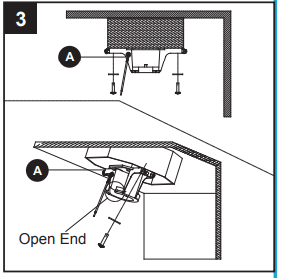
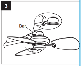
3. Check existing outlet box (not included) to ensure it is securely fastened to at least two points in a structural ceiling member and can support the full weight of the fan. Once verified, install mounting bracket (A) to the outlet box using the screws and washers provided with the outlet box.
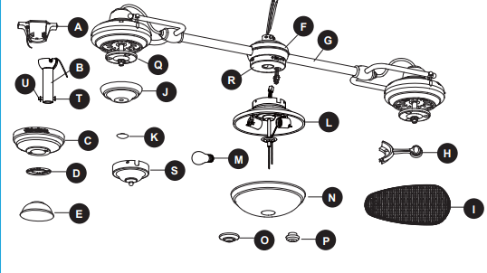
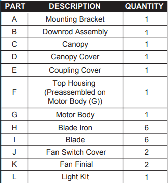
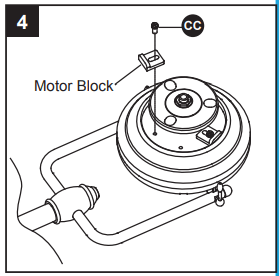
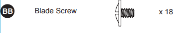
4. Remove the motor body (G) from the protective plastic bag and take the lower packing pad out of the carton. Place the motor body (G) into the packing pad with the bottom of each motor facing up. Remove the motor screws (CC) and motor blocks from each motor of motor body (G). Discard motor blocks and save the motor screws (CC) for later use.
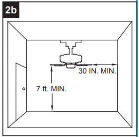
Hardware Used
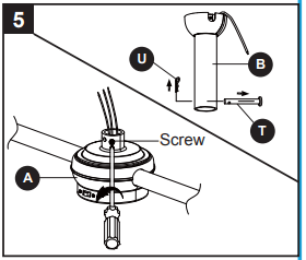
5. Loosen the two coupling screws preassembled in coupling on top housing, but do not remove them. Remove the hairpin clip (U) and clevis pin (T) from the downrod assembly (B). Retain for later use.
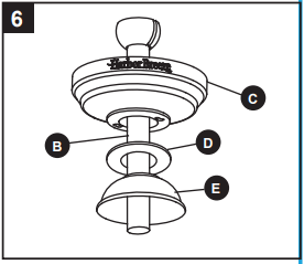
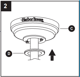
6. Place downrod assembly (B) through canopy (C), canopy cover (D) and coupling cover (E).
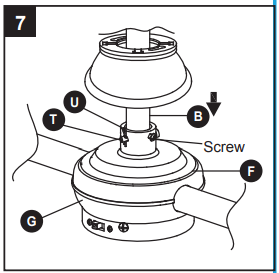
7. Feed power wires from motor body (G) through downrod assembly (B), then insert downrod assembly (B) into the coupling on top housing (F). Align the hole on downrod assembly (B) to hole on coupling, then re-install clevis pin (T). Re-attach hairpin clip (U) into clevis pin (T) until it snaps into place, then tighten the two previously loosened screws on coupling.
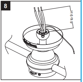
8. Cut off excess fixture wires, leaving approximately 6 to 9 inches above the top of the downrod assembly (B). Strip 1/2 inch insulation from the end of each fixture wire.
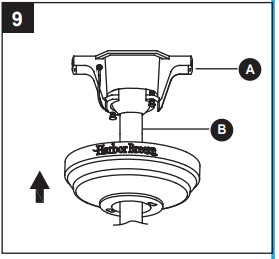
9. Carefully lift the assembly and rest the hanger ball of downrod assembly (B) on the mounting bracket (A) attached to the outlet box.
WIRING INSTRUCTIONS
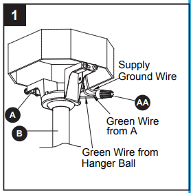
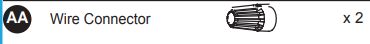
1. Connect the GREEN wires from the hanger ball of downrod assembly (B) and mounting bracket (A) to the supply ground (GREEN or bare color). Securely connect wires using wire connector (AA) supplied.
Hardware Used
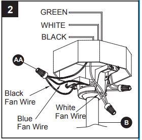
2. Securely connect the fan WHITE wire to the supply WHITE wire using wire connector supplied. Securely connect the fan BLACK and BLUE wires to the supply BLACK wire using wire connector supplied.
Hardware Used
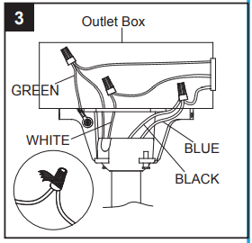
3. Wrap electrical tape (not included) around each wire connector and make sure no bare wire or wire strands are visible after making connections. Then, turn wires upward and carefully push them into the outlet box; make sure the WHITE and GREEN connections are on one side and the BLACK connections are on the other side.
FINAL INSTRUCTIONS
1. Loosen but do not remove the two preassembled mounting screws on mounting bracket (A). Lift canopy (C) up and align the keyholes on the bottom of canopy (C) with mounting screws on mounting bracket (A), then twist canopy (C) clockwise. Tighten mounting screws securely
2. Slide canopy cover (D) over the mounting screws visible in canopy (C). Rotate canopy cover (D) clockwise until it locks into place.
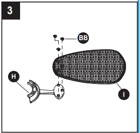
3. Position one blade iron (H) under blade (I). Insert three blade screws (BB) through blade (I) and into blade iron (H). Tighten each blade screw (BB) evenly, starting with the center screw. Repeat for the remaining blade assemblies.
Hardware Used
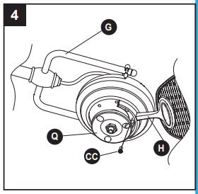
4. Position one completed blade assembly under one motor of motor body (G). Align the holes on motor and blade iron (H) first, then adjust the slot on the switch housing (Q) over the holes. Insert one motor screws (CC) through the slot on the switch housing (Q), and partially tighten. Repeat for the remaining blade assemblies. Securely tighten all motor screws (CC) provided in hardware and previously removed in Step 4 Page 7.
Hardware Used
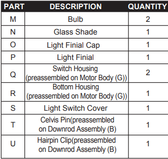
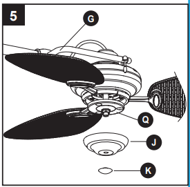
5. Attach the fan switch cover (J) to switch housing (Q) on motor of motor body (G), securing with fan finial (K). Repeat for the other motor of motor body (G).
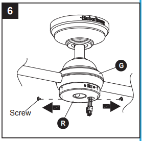
6. Remove three set screws preinstalled on bottom housing (R) of motor body (G) and save them for later use.
To install the fan without the light kit (L), skip to Step 11 (page 14).
To install the fan with the light kit (L), proceed to step 7 (page 12).
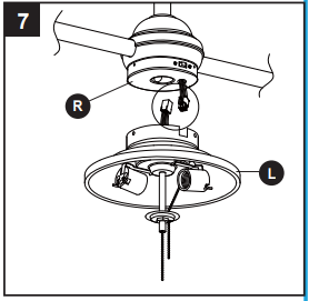
7. To install the light kit (L), attach the connector preassembled on light kit (L) to the connector preassembled on bottom housing (R).
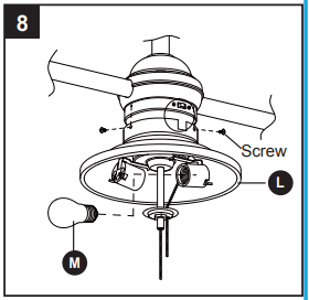
8. Align the cutout on the light kit (L) with the reverse switch on the bottom housing (R). Attach the light kit (L) to the motor housing (G) using the three set screws previously removed (step 6, page 12). Tighten securely, then install bulbs (M) into each socket.
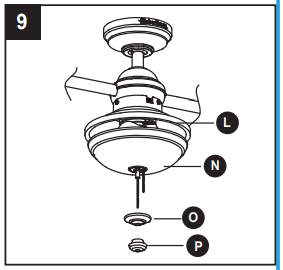
9. Lift the glass shade (N) up to the light kit (L), allowing the preassembled threaded rod and pull chain to go through the hole in the bottom of the glass shade (N). While holding the glass shade (N), guide the threaded rod and pull chain through the appropriate holes on the light finial cap (O). Secure it with light finial (P).
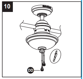
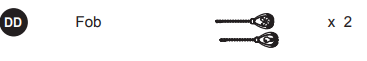
10. Connect the fobs (DD) to the appropriated pull chains. Assembly is now complete.
Hardware Used
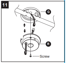
11. For assembly without the light kit (L), remove the preassembled screw in the middle of bottom housing (R) and disassemble bottom housing (R) from motor body (G). Save screw for later use.
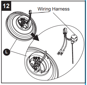
12. Remove the preassembled wiring harness (with pull chain, 6-pin connector and plugs) from the light kit (L).
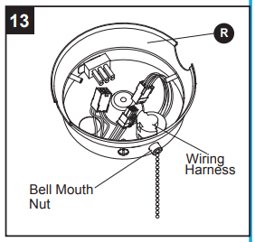
13. Remove the bell mouth nut from pull chain and pass the pull chain leg throuth the round hole on the bottom housing (R). Tighten it with bell mouth nut. Attach the 6-pin connector from the wiring harness to the 6-pin connector preassembled on bottom housing (R).
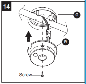
14. Attach the 9-pin connector preassembled on bottom housing (R) to the 9-pin connector from motor body (G). Then, re-attach the bottom housing (R) to the motor body (G) with previously removed screw (Step 11, page 14).
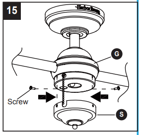
15. Align the cutout on the light switch cover (S) with the pull chain on the bottom housing (R). Attach the light switch cover (S) to the bottom housing (R) with the three set screws previously removed (step 6, page 12). Tighten securely.
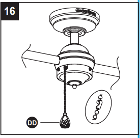
16. Connect the fob (DD) marked with a fan image to the pull chain. You can discard the fob (DD) marked with the light image.
Assembly is now complete.
OPERATING INSTRUCTIONS
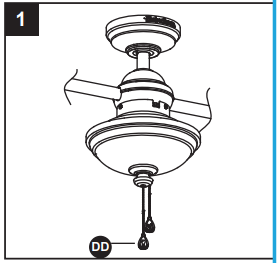
1. The fob (DD) marked with a fan image is for motor speed control: High, Medium, Low and Off. Pull once for each position.
The fob (DD) marked with a lamp image controls the light either On or Off with each pull of the chain.
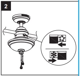
2. When the season changes, you may want to change the direction the fan spins.
In warmer weather, counterclockwise rotation creates a downward airflow, which cools the air. Push the reverse switch located on motor body (G) LEFT and see a SUN icon.
In cooler weather, clockwise rotation creates an upward airflow, which moves hot air from the ceiling. Push the reverse switch located on motor body (G) RIGHT and see a SNOWFLAKE icon.
3. Change the fan angle by adjusting the bars on the two sides, and securely tighten the bars after choosing a predesigned degree.
CARE AND MAINTENANCE
Important : Shut off main power supply before beginning any maintenance. Do not use water or a damp cloth to clean the ceiling fan.
At least twice each year, tighten all screws and lower canopy to check mounting plate screws.
Clean fan housing with only a soft brush or lint-free cloth to avoid scratching the finish. Clean blades with a lint-free cloth. You may occasionally apply a light coat of furniture polish to wood blades for added protection.
Bulb replacement : Use two 6.5-walt max.type A-15 LED bulbs. CFL bulbs are not recommended for this item.
6. The distance from canopy to ceiling is too great.
7. Faulty light bulb installation.
8. Glass is not secure.
1. Tighten all set screws
2. Some fan motors are sensitive to signals from solidstate varible speed controls. DO NOT USE a solid-state variable speed control.
3. Allow "break-in" period of 24 hours. Most noises associated with a new fan will disappear after this period.
4. Check to make sure wire connectors in switch housing are not rattling against each other or against the interior wall of the switch housing
5. Replace blades
6. Make sure upper canopy is a short distance from ceiling. It should not touch the ceiling
7. Make sure light bulb is tight in socket and does not touch on glass shade.
8. Secure the glass
Fan wobbles
1. Hanger bracket and/or ceiling outlet box is not securely fastened
2. Set screw in downrod assembly is loose.
3. Fan hanger ball is not properly seated in canopy tabs
4. Set screw in motor coupling is loose.
5. Blade is loose
6. Blade holders are loose.
7. Blade out of balance
8. Fan too close to vaulted ceiling.
9. Transition to different speed.
10. Fan not securely mounted
1. Tighten the hanger bracket screws to the outlet box, and/or secure outlet box
2. Tighten the set screw in the downrod assembly.
3. Turn power off, support the fan very carefully, and check that the hanger ball is properly seated.
4. Raise motor coupling up and tighten set screws securely
5. Check that all blades are screwed firmly into blade holders
6. Check to be sure the fan blade irons seat firmly and uniformly on the surface of the motor. If flanges are seated incorrectly, loosen the flange screws and
7. Interchange two adjacent blades; this will redistribute the weight and possibly result in smoother operation.
8. Lower or move fan. Extension downrods may be ordered.
9. When switching from medium to low speed, you may notice some fan wobble in the fan. When the fan stabilizes at low speed, wobble should disappear.
10. Make sure canopy and mounting bracket are tightened securely to ceiling joist.
Fan does not start
1. Power turned off, fuse blown or circuit breaker tripped
2. Loose wire connections or wrong connections
3. Motor reversing switch not engaged.
4. Pull chain switch not "on".
1. Turn power on, replace fuse or reset breaker
2a. Turn power off and loosen canopy; check all connections according to section WIRING INSTRUCTIONS on page 9.
2b. Check the plug connection in the switch housing
3. Push switch firmly right or left.
4. Pull switch chain.
Light does not work
1. Wrong wire connection
2. Bulb is burned out
1. Refer to Step 1, page 9 to ensure all wire connections were done correctly