Loading ...
Loading ...
Loading ...
A [mm] * B [mm] *
C [cm
2
] *
D [mm] * E [mm] *
665
x
65 Min. 300 Min. 50 Min. 46
For 700 mm wide appliances:*
A [mm]* B [mm]*
C [cm
2
]*
D [mm]* E [mm]*
665
x
65 min. 300 min. 50 min. 46
x
If wall spacers are used, the dimensions increase by 15 mm
(see 4.2) .
The dimensions apply for an opening angle of 90 °. Spacing
angles will vary according to the opening angle.
The appliance can be built into kitchen units. A top cupboard
Fig. 25 (2)
can be added above the appliance in order to bring
the appliance
Fig. 25 (1)
up to the height of the fitted kitchen
units.
The appliance can be installed right next to the kitchen cabinet
Fig. 25 (3)
. The appliance must stick out by the depth
Fig. 25 (B)
from the front of the cabinet so that the doors can be
opened fully. The appliance may protrude further depending on
the depth of the kitchen cabinets and whether wall spacers are
used.
NOTICE
Danger of overheating due to insufficient air ventilation!
The compressor may be damaged if there is insufficient air
ventilation.
u
Take care to ensure adequate air ventilation.
u
Observe the ventilation requirements.
Ventilation requirements:
-
Spacer ribs on the back of the appliance provide sufficient
air ventilation. In the final appliance position, these must not
be placed in recesses or cut-outs.
-
There must be a ventilation shaft with the depth
Fig. 25 (D)
at the back of the top cupboard over the entire width of the
cupboard.
-
The ventilation shaft
Fig. 25 (C)
must be observed under the
ceiling.
-
the larger the ventilation space, the more energy-saving the
appliance is in operation.
If the appliance is installed with the hinges next to a wall
Fig. 25 (4)
the distance
Fig. 25 (E)
between the appliance and
the wall must be observed. This is how far the handle protrudes
when the door is open.
4.5 Disposing of packaging
WARNING
Danger of suffocation due to packing material and plastic film!
u
Do not allow children to play with packing material.
The packaging is made of recyclable materials:
-
corrugated board/cardboard
-
expanded polystyrene parts
-
polythene bags and sheets
-
polypropylene straps
-
nailed wooden frame with polyethylene panel*
u
Take the packaging material to an official collecting point.
4.6 Connecting the appliance
WARNING
Failure to connect properly
Fire hazard.
u
Do not use an extension cable.
u
Do not use distributor blocks.
NOTICE
Failure to connect properly
Damage to the electronics.
u
Do not use a standalone inverter.
u
Do not use an energy saving plug.
Note
Only use the power connection lead supplied.
u
A longer power connection lead can be ordered from
Customer Service.
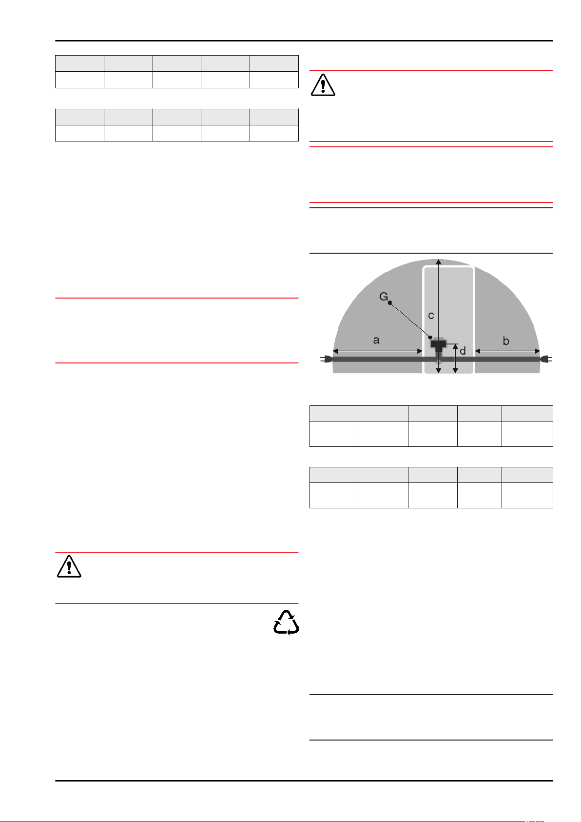
Fig. 26
For 600 mm wide appliances:*
a* b* c* d* G*
~ 1800 mm ~ 1400 mm ~ 2100 mm ~ 200 mm Appliance
plugs
For 700 mm wide appliances:*
a* b* c* d* G*
~ 1750 mm ~ 1350 mm ~ 2100 mm ~ 200 mm Appliance
plugs
Ensure that the following conditions are met:
- The type of current and voltage at the installation site corre-
spond to the information on the model plate (see 1) .
- The socket is earthed according to the regulations and
fused.
- The fuse tripping current is between 10 and 16 A.
- The socket is easily accessible.
- The socket is outside the back of the appliance area in the
specified area
Fig. 26 (a, b, c)
.
u
Check the electrical connection.
u
Insert the appliance plug
Fig. 26 (G)
into the back of the
appliance. Ensure that it clicks into place.
u
Connect the power plug to the power supply.
w
The Liebherr logo appears on the screen.
w
The display switches to the standby symbol.
4.7 Switching on the appliance
Note
If the appliance is in demo mode, DEMO appears on the home-
screen.
u
Disable demo mode (see 7) .
Putting into operation
14 * Depending on model and options
Loading ...
Loading ...
Loading ...