Loading ...
Loading ...
Loading ...
u
Carefully lift up the plugs with a slotted screwdriver and
remove them.
Fig. 21 (1)
u
Insert the plugs again on the other side of the door.
Fig. 21 (2)
u
Position the door from above onto the lower bearing pins.
Fig. 21 (3)
u
Insert the centre bearing pin through the centre bearing
bracket into the lower door. Make sure that the catch mecha-
nism is pointing to the rear.
Fig. 21 (4)
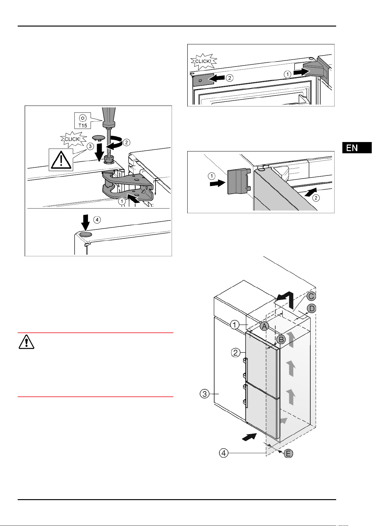
4.3.9 Fitting the upper door
Fig. 22
u
Place the door on the centre bearing pins.
u
Align the top of the door with opening in the bearing bracket.
Fig. 22 (1)
u
Insert the bolt and tighten with a T15 screwdriver.
Fig. 22 (2)
u
Fit the protective cover to protect the door: Insert the protec-
tive cover and check that it is attached to the door. If not,
insert the bolt fully.
Fig. 22 (3)
u
Insert the plugs.
Fig. 22 (4)
4.3.10 Aligning the doors
WARNING
Risk of injury due to the door dropping out!
If the bearing parts are not screwed into place firmly enough,
the door may drop out. This may lead to severe injuries. What is
more, the door may not close and therefore the appliance may
fail to cool properly.
u
Screw the turn hinges firmly into place with 4 Nm.
u
Check all of the screws and retighten if necessary.
u
Align the doors flush with the appliance housing using the
two oblong holes in the lower bearing bracket and centre
bearing bracket if needed. To do this undo the middle screw
in the bottom bearing bracket with the T25 tool supplied.
Undo the remaining screws a little with the T25 tool or with a
T25 screwdriver and align using the slotted holes. Undo the
screws in the middle bearing bracket with the T25 tool and
align the middle bearing bracket using the slotted holes.
u
Support the door: Take off the adjustable foot on the bearing
bracket using the open-ended wrench SW10 until it comes
into contact with the floor, then turn an additional 90°.
4.3.11 Fit the covers
Fig. 23
The door is open 90°.
u
Position the bearing bracket and engage. If necessary push
apart carefully.
Fig. 23 (1)
u
Position the panel on the side and click into place.
Fig. 23 (2)
Fig. 24
u
Slide on the external cover.
Fig. 24 (1)
u
Close the upper door.
Fig. 24 (2)
4.4 Insertion into a row of kitchen units
Fig. 25
For 600 mm wide appliances:*
Putting into operation
* Depending on model and options 13
Loading ...
Loading ...
Loading ...