Loading ...
Loading ...
Loading ...
58
ENGLISH
Checking procedure of limiting concentration
Check concentration limit along following steps and take appropriate
measure depending on the situation.
Calculate amount of all the replenished refrigerant [kg (lbs)] per each
refrigerant system.
Concentration limit is the limit of Freon gas concentration where
immediate measures can be taken without hurting human body
when refrigerant leaks in the air. The Concentration limit shall be
described in the unit of [kg/m
3
(lbs/ft
3
)] (Freon gas weight per unit
air volume) for facilitating calculation.
Concentration limit: 0.44 kg/m
3
(0.028 lbs/ft
3
) (R410A)
Amount of additional
replenished refrigerant
Total amount of refrigerant
in in the system [kg (lbs)]
+
=
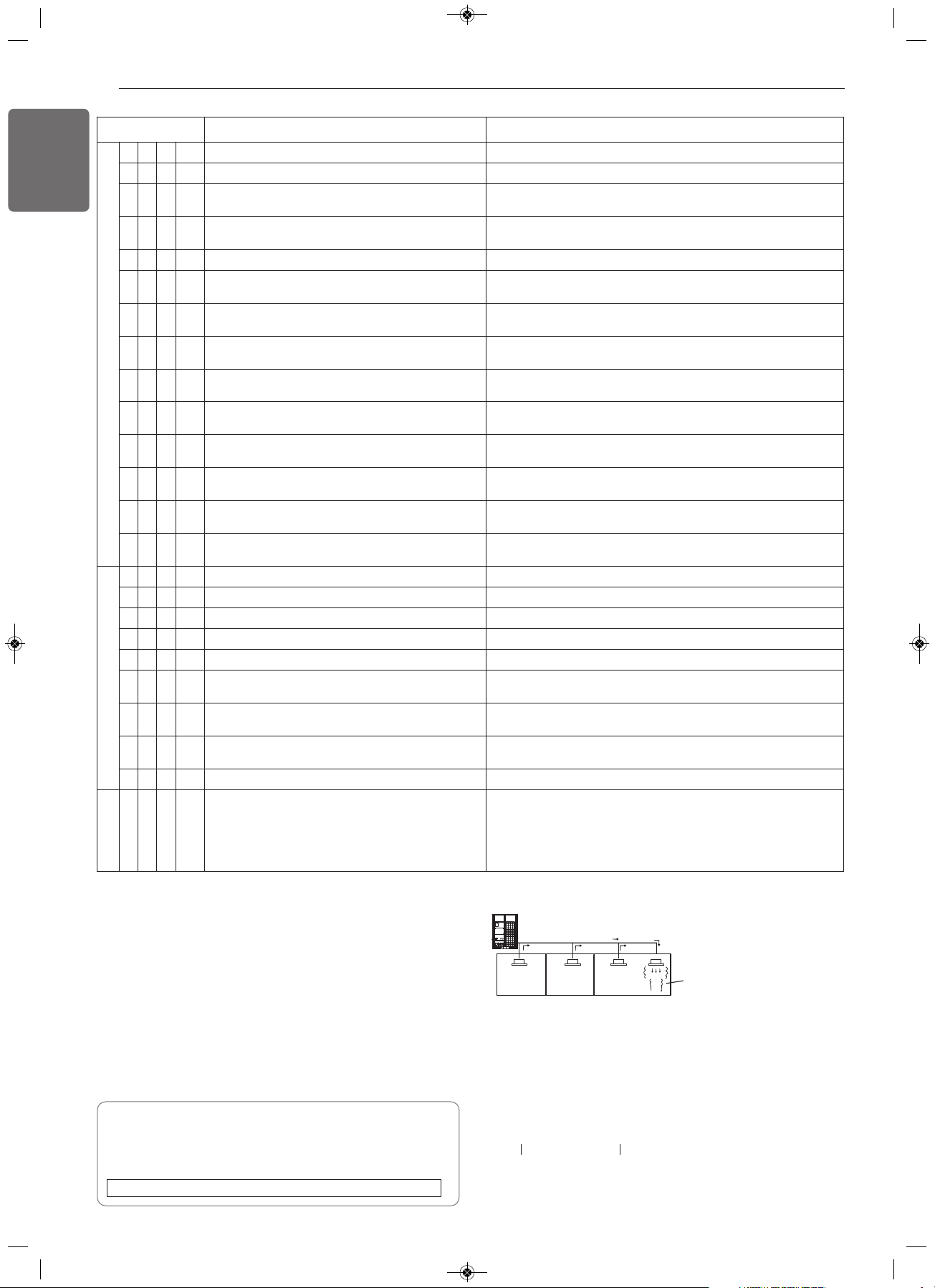
Note : In case one refrigerant facility is
divided into 2 or more refrigerant
systems and each system is
independent, amount of replenished
refrigerant of each system shall be
adopted.
Amount of pre-charged
refrigerant per single
Amount of replenished
refrigerant at factory shipment
Amount of additionally
replenished refrigerant
depending on piping
length or piping
diameter by customer
Outdoor unit
(No.1 system)
Flow of
refrigerant
Indoor unit
Room where refrigerant leaks
(Refrigerant of the whole No.1
system flows out.)
CAUTION FOR REFRIGERANT LEAK
The installer and system specialist shall secure safety against leakage
according to local regulations or standards.
The following standards may be applicable if local regulations are not
available.
Introduction
Though the R410A refrigerant is harmless and incombustible itself ,
the room to equip the air conditioner should be large to such an extent
that the refrigerant gas will not exceed the concentration limit even if
the refrigerant gas leaks in the room.
Concentration limit
h : HR unit # : HR unit number
Display Title Cause of Error
Outdoor unit related error
1 0 7* Outdoor Unit Fan DC Link Low Voltage Error Outdoor Unit Fan DC Link Input Voltage is under 380 V
1 1 3* Outdoor Unit Liquid pipe Temperature Sensor Error Liquid pipe temperature sensor of Outdoor Unit is open or short
1 1 4*
Outdoor Unit Subcooling Inlet Temperature Sensor
Error
Outdoor Unit Subcooling Inlet Temperature Sensor Error
115 *
Outdoor Unit Subcooling Outlet Temperature
Sensor Error
Outdoor Unit Subcooling Outlet Temperature Sensor Error
1 1 6 * Outdoor Unit Oil Level Sensor Error Oil Level Sensor of Outdoor Unit is open or short
145 *
Outdoor unit Main Board - External Board
communication Error
Outdoor unit Main Board - External Board communication Error
1 5 0 * Outdoor Unit Discharge Superheat not satisfied
Outdoor Unit Compressor Discharge Superheat not satisfied
during 5 Min.
151 *
Failure of operation mode conversion at Outdoor
Unit
Failure of operation mode conversion at Outdoor Unit
153 *
Outdoor Unit Heat Exchanger Temperature Sensor
(upper part) Fault
Outdoor Unit Heat Exchanger Temperature Sensor (upper part)
Fault
154 *
Outdoor Unit Heat Exchanger Temperature Sensor
(lower part) Fault
Outdoor Unit Heat Exchanger Temperature Sensor(lower part)
open or short
182 *
Outdoor unit External Board Main-Sub Micom
communication Error
Outdoor Unit Main Board Main-Sub Micom communication failed
1 8 7 * Hydro - Kit P,HEX bursting error
Inlet water temperature is below 5 degree or water temperature
error during defrosting operation.
1 9 3 * Outdoor Unit Fan Heatsink High Temperature
System is turned off by Outdoor Unit Fan Heatsink High
Temperature
194 *
Outdoor Unit Fan Heatsink Temperature Sensor
Fault
Outdoor Unit Fan Heatsink Temperature Sensor open or short
HR Unit related error
2 0 0 1 Searching pipe Error Failure of automatic addressing of valves
201
#HR + h
HR unit1 Liqiud sensor error Liquid pipe sensor of HR unit open or short
202
#HR + h
HR unit1 Sub Cooling Pipe sensor error Sub Cooling Pipe In sensor of HR unit open or short
203
#HR + h
HR unit1 Sub Cooling Pipe Out sensor error Sub Cooling Pipe Out sensor of HR unit. open or short
204
#HR + h
Communication error Failing to receive HR unit signal at outdoor unit
205
#HR + h
Communication error between HR unit and the
upgraded 485 modem.
4 series upgraded 485 communication error between
HR unit and HR unit modem
206
#HR + h
Duplicate address error of HR unit
When the HR unit address is set duplicated at the 4 series
upgraded 485 communication
207
#HR + h
Communication error between Master and Slave
Main PCB of HR Unit
When fail to communication between Master and Slave Main PCB
of HR Unit
208
#HR + h
Communication error of EEPROM of HR Unit When fail to communication of EEPROM of HR Unit
Network error
2 4 2 * Network error of cntral controller Communication wiring defect
1,MFL68980308,영영 2018. 11. 13. 영영 3:24 Page 58
Loading ...
Loading ...