Loading ...
Loading ...
Loading ...
37
ENGLISH
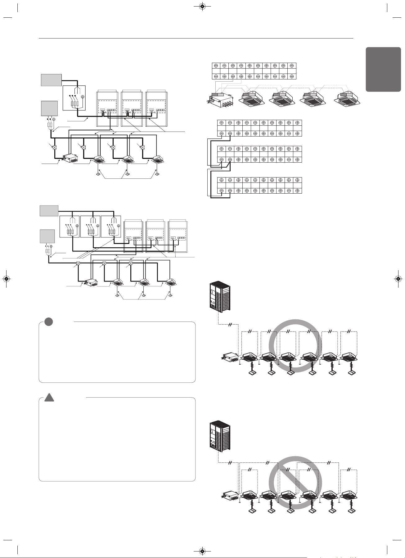
Master
Outdoor Unit
SODU. B SODU. A IDU. B IDU. A CEN. B CEN. A DRY1 DRY2 GND 12V
SODU. B SODU. A IDU. B IDU. A CEN. B CEN. A DRY1 DRY2 GND 12V
SODU. B SODU. A IDU. B IDU. A CEN. B CEN. A DRY1 DRY2 GND 12V
Master
Outdoor Unit
SODU. B SODU. A IDU. B IDU. A CEN. B CEN. A DRY1 DRY2 GND 12V
Slave1
Outdoor Unit
HR unit
AB
Slave2
Outdoor Unit
3(A) 4(B) 3(A) 4(B) 3(A) 4(B) 3(A) 4(B)
Between Indoor and Master Outdoor unit
• It is not the point to make ground connection.
- Make sure that terminal number of master and slave outdoor units
are matched.(A-A,B-B)
WARNING
• Indoor unit ground lines are required for preventing electrical shock
accident during current leakage, Communication disorder by noise
effect and motor current leakage (without connection to pipe).
• Don't install an individual switch or electrical outlet to disconnect
each of indoor unit separately from the power supply.
• Install the main switch that can interrupt all the power sources in an
integrated manner because this system consists of the equipment
utilizing the multiple power sources.
• If there exists the possibility of reversed phase, lose phase,
momentary blackout or the power goes on and off while the product
is operating, attach a reversed phase protection circuit locally.
Running the product in reversed phase may break the compressor
and other parts.
!
3 Outdoor Units-3 Ø, 460 V / 575 V
When the power source is connected In series between the units.
Switch
Communication Line
(2 Wires Cable)
Power Line
(3 Wires Cable)
Communication Line
(3 Wires Cable)
Power Line
(2 Wires Cable)
Power Line
(2 Wires Cable)
Power Line
(2 Wires Cable)
Power Line
(2 Wires Cable)
[Master]
[Indoor Units]
Power supply
3 Phase 3 Wires
60 Hz 460 V / 575 V
Power supply
1 Phase 60 Hz
208/230 V
(Main Switch)
[Slave1] [Slave2]
Switch Switch
ELCB ELCB ELCB
Pull box
(Installer option)
Pull box
(Installer option)
Pull box
(Installer option)
Power Line
(2 Wires Cable)
HR unit
ELCB
L(L1) N(L2)
R(L1)
S(L2) T(L3)
R(L1)
S(L2) T(L3)
R(L1)
S(L2) T(L3)
Communication Line
(2 Wires Cable)
Power Line
(3 Wires Cable)
Communication Line
(3 Wires Cable)
Power Line
(2 Wires Cable)
Power Line
(2 Wires Cable)
Power Line
(2 Wires Cable)
Power Line
(2 Wires Cable)
Power Line
(2 Wires Cable)
[Master]
[Indoor Units]
(Main Switch)
[Slave1] [Slave2]
Pull Box
(Installer option)
Pull Box
(Installer option)
Pull Box
(Installer option)
Pull Box
(Installer option)
HR unit
Switch
ELCB
ELCB
Power supply
3 Phase 3 Wires
60 Hz 460 V / 575 V
Power supply
1 Phase 60 Hz
208/230 V
L(L1) N(L2)
R(L1)
S(L2) T(L3)
When the power source is supplied to Each outdoor unit individually.
NOTE
!
- Field wiring diagram is to be used as a guideline only. Wiring
should comply with applicable local and national codes
- ELCB must have function to prevent electrical short and over
current at the same time.
- Use copper wires only.
- Unit must be grounded in compliance with the applicable local
and national codes.
- ELCB and fuse/breaker must install to the power line
Example) Connection of transmission wire
[BUS type]
- Connection of communication cable must be installed like below
figure between indoor unit to outdoor unit.
HR unit
HR unit
[STAR type]
- Abnormal operation can be caused by communication defect, when
connection of communication cable is installed like below figure.
1,MFL68980308,영영 2018. 11. 13. 영영 3:23 Page 37
Loading ...
Loading ...
Loading ...