Loading ...
Loading ...
Loading ...
33
ENGLISH
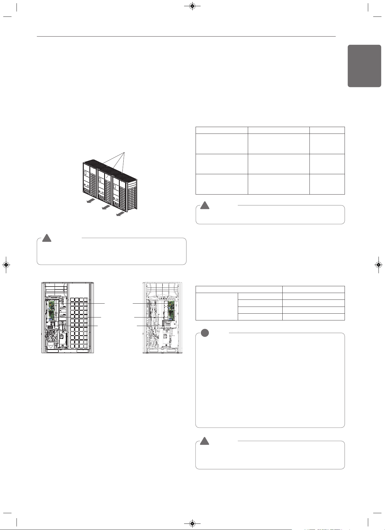
Front Panel
UXA
UXB
Main Board
External Board
Main power line
terminal block
(Take care of the phase
sequence of 3-phases
3-wires power system)
WARNING
The temperature sensor for outdoor air should not be exposed to
direct sunlight.
- Provide an appropriate cover to intercept direct sunlight.
!
NOTE
!
• The figures are based on assumed length of parallel cabling up
to 100 m [328 ft]. For length in excess of 100 m [328 ft] the
figures will have to be recalculated in direct proportion to the
additional length of cable involved.
• If the power supply waveform continues to exhibit some
distortion the recommended spacing in the table should be
increased.
- If the cable are laid inside conduits then the following point
must also be taken into account when grouping various cable
together for introduction into the conduits
- Power cable(including power supply to air conditioner) and
communication cables
must not be laid inside the same
- In the same way, when grouping the power wires and
communication cables should not be bunched together.
Separation of communication and power cables
- If communication and power cables are installed alongside each other
then there is a strong likelihood of operational faults developing due
to interference in the signal wiring caused by electrostatic and
electromagnetic coupling.
The tables below indicates our recommendation as to appropriate
spacing of communication and power cables where these are to be
run side by side
Communication and Power Cables
Communication cable
- Types : shielded wires or unshielded wires
- Cross section : 1.0 ~ 1.5 mm
2
(1.55 × 10
-3
~ 2.32 × 10
-3
in
2
)
- Maximum allowable temperature: 60 °C (140 °F)
- Maximum allowable cable length: under 1 000 m (3 281 ft)
Remote control cable
- Types : 3-core cables
Central control cable
Product type Cable type Diameter
ACP&AC Manager
2-core cable (Shielding cable)
1.0 ~ 1.5 mm
2
(1.55 × 10
-3
~
2.32 × 10
-3
in
2
)
AC Smart
2-core cable (Shielding cable)
1.0 ~ 1.5 mm
2
(1.55 × 10
-3
~
2.32 × 10
-3
in
2
)
Simple central controller
4-core cable (Shielding cable)
1.0 ~ 1.5 mm
2
(1.55 × 10
-3
~
2.32 × 10
-3
in
2
)
Current capacity of power cable Spacing
100 V or more
10 A 300 mm (11-13/16 inch)
50 A 500 mm (19-11/16 inch)
100 A 1 000 mm (39-3/8 inch)
Exceed 100 A 1 500 mm (59-1/16 inch)
Control box and connecting position of wiring
- Remove all of the screws at front panel and remove the panel by
pulling it forward.
- Connect communication cable between main and slave outdoor unit
through the terminal block.
- Connect communication cables between outdoor unit and indoor
units through the terminal block.
- When the central control system is connected to the outdoor unit, a
dedicated PCB must be connected between them.
- When connecting communication cable between outdoor unit and
indoor units with shielded cable, connect the shield ground to the
earth screw.
- Be sure to also make grounding connections to ground screws when
connecting shielded wires to the central control system.
In case of using the shielded wires, it should be grounded.
CAUTION
!
If apparatus is not properly earthed then there is always a risk of
electric shock, the grounding of the apparatus must be carried out by
a qualified person.
CAUTION
!
1,MFL68980308,영영 2018. 11. 13. 영영 3:23 Page 33
Loading ...
Loading ...
Loading ...