Loading ...
Loading ...
Loading ...
44
ENGLISH
SW01E
SW #1 On : Select Valve #1
Master
ON
OFF
SW02B SW01B
Input the central control
address of Indoor unit
Master
SW01E
SW #1 Off : Finish Valve #1
Master
ON
OFF
SW01E
SW #2 On : Select Valve #6
Slave
ON
OFF
SW02B SW01B
Input the central control
address of Indoor unit
Slave
SW01E
SW #2 Off : Finish Valve #6
Slave
ON
OFF
1 Normal setting (Non-Zoning setting)
ex) Manual pipe detection of Valve #1, 6.
2 Zoning setting
SW01E
SW #1 On : Select Valve #5
Slave
ON
OFF
SW02B SW01B
SW01C
After selecting No.1 zoning
indoor unit, input the central
control address of indoor unit.
Slave
After selecting No.2 zoning
indoor unit, input the central
control address of indoor unit.
Setting SW01C to ‘0’After selecting No.3 zoning
indoor unit, input the central
control address of indoor unit.
SW01E
SW #1 Off : Finish Valve #5
Slave
ON
OFF
SW01E
SW #2 On : Select Valve #6
Slave
ON
OFF
SW02B SW01B
Input the central control
address of Indoor unit
Slave
SW01E
SW #2 Off : Finish Valve #6
Slave
ON
OFF
0
SW02B
SW01C
SW01B
Slave
1
SW01C
Slave
0
SW02B
SW01C
SW01B
Slave
2
ex) Manual pipe detection of Valve #5 with three zoning indoor units,
#6 without zoning unit.
NOTE
!
Use the Zoning Control when install two or more indoor units at 1
branch of HR Unit.
The indoor units controlled by Zoning Control can be selected
collectively as the cooling / heating mode.
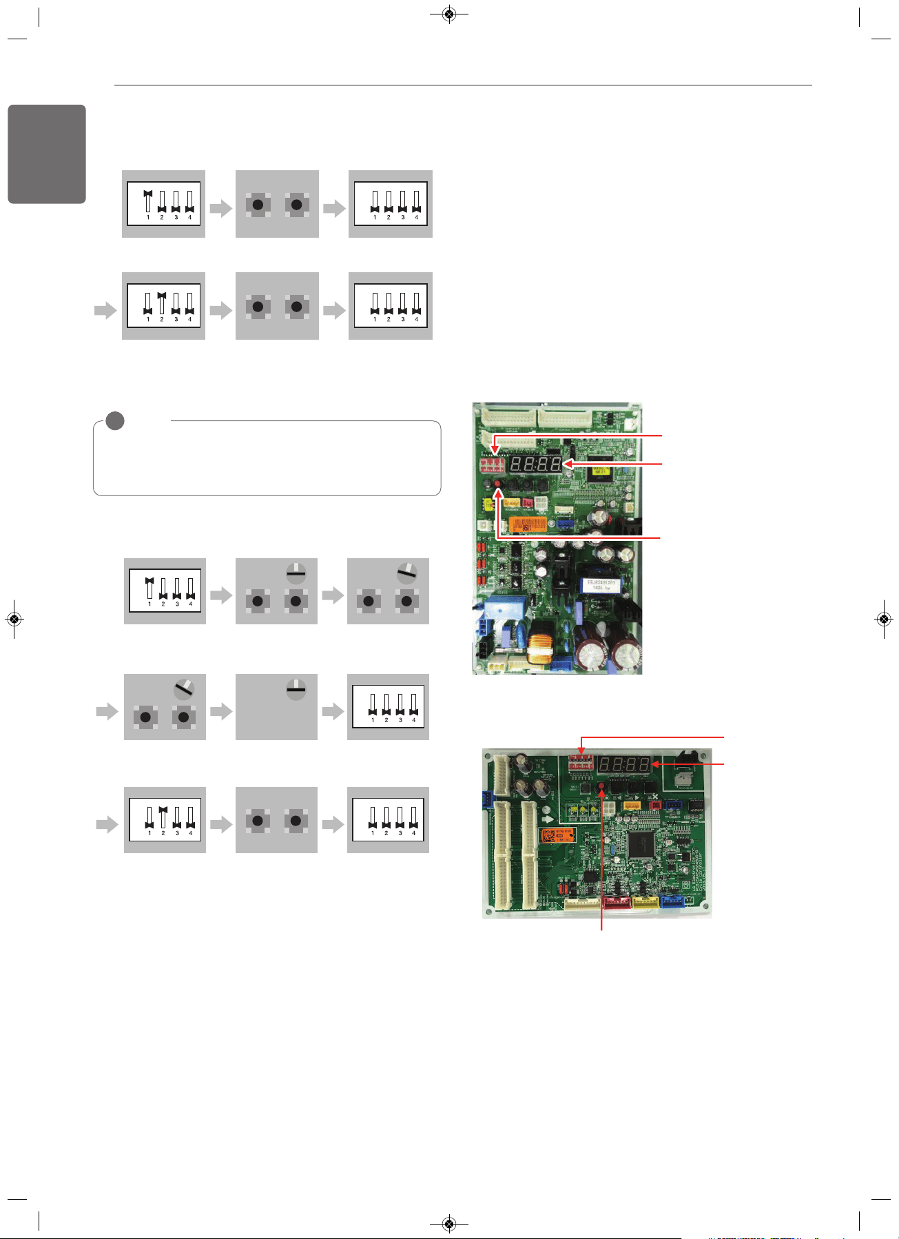
DIP switch
7 segment
SW01C
(Automatic Addressing Setting)
Automatic Addressing
The address of indoor units would be set by Automatic
Addressing
- Wait for 3 minutes after supplying power.
(Master and Slave outdoor units, indoor units)
- Press RED button of the outdoor units for 5 seconds. (SW01C)
- A “88” is indicated on 7-segment LED of the outdoor unit PCB.
- For completing addressing, 2~7 minutes are required depending on
numbers of connected indoor units
-
Numbers of connected indoor units whose addressing is completed are
indicated for 30 seconds on 7-segment LED of the outdoor unit PCB
- After completing addressing, address of each indoor unit is indicated
on the wired remote control display window. (CH01, CH02,
CH03, ……, CH06 : Indicated as numbers of connected indoor units)
[Main Board]
ARUM***B(D)TE5
ARUM***CTE5
DIP switch
7 Segmen
t
SW01C
(Automatic Addressing Setting)
1,MFL68980308,영영 2018. 11. 13. 영영 3:24 Page 44
Loading ...
Loading ...
Loading ...